


ADCP-75-237 • Issue 1 • 8/2007 • Section 3: Graphical User Interface
Page 3-10
© 2007, ADC Telecommunications, Inc.
4
US_PCS TEST SCREEN
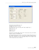
The Testing screen is opened by pressing the “F5” Function key. This window is used to test
each attenuation, and test band selection or set PLL.
4.1
Fwd Base Volt
Input 0dB signal to the repeater system, and click 0dB “Read” button. This will read the
forward path voltage and show in the text box.
Input +1dB signal to the repeater system, and click +1dB-”Read” button. This will read the
forward path voltage and show in the text box.
Input –1dB signal to the repeater system, and click -1dB-”Read” button. This will read the
forward path voltage and show in the text box.
After all three values are read, “Balance” button will become active. By pressing the “Balance”
button, the program automatically calculates the voltage difference of 0dB, +1dB, and -1dB
situation, and print in the text box beside the “Balance” button.
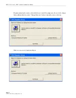
After the balance voltage value has been printed in the text box, “Write” button will become
active. Pressing the “Write” button will save the voltage values to the repeater system memory.
Содержание ADCP-75-237
Страница 1: ...ADC In Building 850 and 1900MHz Wireless Repeater User Manual 1xxxxxx Rev A ADCP 75 237 Issue 1 8 2007...
Страница 2: ......
Страница 3: ...ADC In Building 850 and 1900MHz Wireless Repeater User Manual ADCP 75 237 Issue 1 8 2007 1xxxxxx Rev A...
Страница 12: ...ADCP 75 237 Issue 1 8 2007 Preface Page xii 2007 ADC Telecommunications Inc...
Страница 20: ...ADCP 75 237 Issue 1 8 2007 Section 2 Installation Page 2 4 2007 ADC Telecommunications Inc...
Страница 32: ...ADCP 75 237 Issue 1 8 2007 Section 3 Graphical User Interface Page 3 12 2007 ADC Telecommunications Inc Blank...
Страница 35: ......


