background image

ADCP-75-237 • Issue 1 • 8/2007 • Section 2: Installation

Page 2-1

© 2007, ADC Telecommunications, Inc.

SECTION 2: INSTALLATION


Content

Page

1

REPEATER INSTALLATION  . . . . . . . . . . . . . . . . . . . . . . . . . . . . . . . . . . . . . . . . . . . . . . . . . . . . . . . . . . . . . . . .2-1

1.1

Mechanical Attachment of Repeater. . . . . . . . . . . . . . . . . . . . . . . . . . . . . . . . . . . . . . . . . . . . . . . . . . . .2-1

1.1.1

Standard Wall Mount . . . . . . . . . . . . . . . . . . . . . . . . . . . . . . . . . . . . . . . . . . . . . . . . . . . . . .   2-1

1.1.2

Masonry Wall Mount  . . . . . . . . . . . . . . . . . . . . . . . . . . . . . . . . . . . . . . . . . . . . . . . . . . . . . .   2-1

1.2

Installation of Repeater Cables . . . . . . . . . . . . . . . . . . . . . . . . . . . . . . . . . . . . . . . . . . . . . . . . . . . . . . .2-2

_________________________________________________________________________________________________________

1

REPEATER INSTALLATION

The repeater should be mounted in accordance with local code using appropriate hardware 
(customer provided). Repeater must be installed within six feet of an AC power source (100–240 
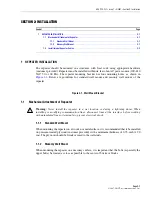
VAC 50 or 60 Hz). The repeater mounting bracket has four mounting holes, as shown in 

Figure 2-1

. Below are guidelines for standard wall mount and masonry wall mount of the 

repeater.

Figure 2-1. Wall Mount Bracket

1.1

Mechanical Attachment of Repeater

Warning: 

Never install the repeater in a wet location or during a lightning storm. When 

installing or modifying communication lines, disconnect lines at the interface before working 
with uninsulated lines or terminals to prevent electrical shock.

1.1.1

Standard Wall Mount

When mounting the repeater on a wooden or metal surface, it is recommended that it be installed 
on pressure-treated plywood (customer provided) with a minimum thickness of 0.75–inch (19.0 
cm). The plywood should be firmly secured to the wall studs.

1.1.2

Masonry Wall Mount

When mounting the repeater on a masonry surface, it is important that the bolts (especially the 
upper bolts) be located as 

close as possible to the center of bricks or blocks

.

Содержание ADCP-75-237

Страница 1: ...ADC In Building 850 and 1900MHz Wireless Repeater User Manual 1xxxxxx Rev A ADCP 75 237 Issue 1 8 2007...

Страница 2: ......

Страница 3: ...ADC In Building 850 and 1900MHz Wireless Repeater User Manual ADCP 75 237 Issue 1 8 2007 1xxxxxx Rev A...

Страница 4: ...prior notice In no event shall ADC be liable for any damages resulting from loss of data loss of use or loss of profits and ADC further disclaims any and all liability for indirect incidental special...

Страница 5: ...SCRIPTION 1 1 1 1 RF SIGNAL FLOW 850MHz 1 1 1 2 RF SIGNAL FLOW 1900MHz 1 2 2 FEATURES 1 3 2 1 LED Status 1 3 2 2 Automatic Level Control ALC 1 3 2 3 Sleep Mode 1 3 2 4 Isolation Check 1 3 2 5 Over Pow...

Страница 6: ...Band Selection 3 11 4 4 Attenuation Test MGC ALC Control 3 11 4 5 Gain Offset Box 3 11 4 6 Fwd PLL Attenuation Control 3 11 4 7 Rev Pll Attenuation Control 3 11 SECTION 4 GENERAL INFORMATION 1 WARRAN...

Страница 7: ...ion Caution is used to indicate the presence of a hazard that will or can cause minor personal injury or property damage if the hazard is not avoided GENERAL SAFETY PRECAUTIONS List here all general a...

Страница 8: ...It has been tested and found to comply with limits for a Class A digital device pursuant to Subpart B of Part 15 of FCC Rules which are designed to provide reasonable protection against such interfere...

Страница 9: ...of UL CSA 60950 XXX modules and chassis have been tested and found to comply with all applicable CE Directives XXXX complies with the requirements of GR 63 CORE Issue 1 October 1995 and GR 1089 CORE I...

Страница 10: ...ss 1 LASER according to FDA CDRH Rules This product conforms to all applicable standards of 21 CFR Part 1040 IC This equipment complies with the applicable sections of RSS 131 The term IC before the r...

Страница 11: ...Amplifier PAA Power Amplifier Assembly PC Personal Computer PCI Peripheral Component Interconnect bus PIC PA Interface Controller P MCPLR PCS Multicoupler RAN Radio Access Node RDC RAN Down Converter...

Страница 12: ...ADCP 75 237 Issue 1 8 2007 Preface Page xii 2007 ADC Telecommunications Inc...

Страница 13: ...ted on a rooftop or external wall of a building directed at the donor cell site The repeater is mounted inside the building and distributes the RF over coax to an indoor antenna located in the desired...

Страница 14: ...through a BPF Band Pass Filter then is amplified by the drive amplifier The signal than goes through the LNA and a Down Mixer where IF signal conversion is done This IF signal then goes through an IF...

Страница 15: ...k Isolation check LED for the forward path and reverse path comes on after the Donor antenna is set up and the power is turned on Automatic Gain set up is available within the repeater for the Path Is...

Страница 16: ...45 846 5 B 891 5 894 846 5 849 2 6 2 1900MHZ Repeater Band Selection Band selection is available within the US PCS 60MHz bandwidth You can select any A B or C band 15MHz each group1 and any D E or F b...

Страница 17: ...hown in Figure 2 1 Below are guidelines for standard wall mount and masonry wall mount of the repeater Figure 2 1 Wall Mount Bracket 1 1 Mechanical Attachment of Repeater Warning Never install the rep...

Страница 18: ...connectors one power connector and one USB port A USB cable is required when configuring the repeater using the GUI Plug one end of the USB cable into the port on the bottom of the repeater and plug t...

Страница 19: ...PDU ALARM connector 4 Connect the power cable to the site DC power connector The power cable has three leads Red is positive Black is negative and Yellow Green is for ground 5 Connect the power cable...

Страница 20: ...ADCP 75 237 Issue 1 8 2007 Section 2 Installation Page 2 4 2007 ADC Telecommunications Inc...

Страница 21: ...Volt 3 10 4 2 Rev Base Volt 3 11 4 3 Band Selection 3 11 4 4 Attenuation Test MGC ALC Control 3 11 4 5 Gain Offset Box 3 11 4 6 Fwd PLL Attenuation Control 3 11 4 7 Rev Pll Attenuation Control 3 11 __...

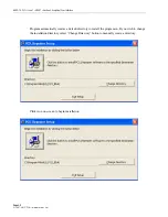
Страница 22: ...3 2 2007 ADC Telecommunications Inc Program automatically creates a default directory to install the program in If you wish to change the installation directory select Change Directory button to manu...

Страница 23: ...7 Section 3 Graphical User Interface Page 3 3 2007 ADC Telecommunications Inc Choose a Program Group where program is to be installed By default the program creates a new program group named Pcs_Repea...

Страница 24: ...cations Inc If this software program is using an older window database there is a version conflict Keep the original file by clicking Yes Successful installation completed Click OK button The window w...

Страница 25: ...to Windows Start menu Program Pcs_Repeater program group Click Pcs_Repeater to start program The following screen displays the start window of the program 2 1 Menu Information Setting Connection opti...

Страница 26: ...n output power is equal to or higher than the registered value the signal button turns red Isolation Check RUN button is active Pressing the RUN button starts the isolation check When the Isolation Ch...

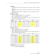
Страница 27: ...art Freq Lo Freq stop Freq start Freq Lo Freq stop Freq A A 869 951 5 880 824 951 5 835 B 880 890 835 845 A 890 891 5 845 846 5 B 891 5 894 846 5 849 1900MHz Band Selection A B C x 15MHz path band A B...

Страница 28: ...the connected port number Properties Window bottom line Properties shows the property information Note You must install a USB driver to use the USB port After installing the driver the software recog...

Страница 29: ...t None H W Select both All options may use default settings except for Port You must select correct port that the computer is connected to the equipment with After finishing the selection press OK to...

Страница 30: ...system and click 1dB Read button This will read the forward path voltage and show in the text box Input 1dB signal to the repeater system and click 1dB Read button This will read the forward path volt...

Страница 31: ...4 4 Attenuation Test MGC ALC Control Press up down arrow key to adjust the Manual Gain Control in 0 5dB increments Press up down arrow key to adjust the Automatic Level Control in 0 5dB increments 4 5...

Страница 32: ...ADCP 75 237 Issue 1 8 2007 Section 3 Graphical User Interface Page 3 12 2007 ADC Telecommunications Inc Blank...

Страница 33: ...ducts are available at a nominal fee Contact the Technical Assistance Center at 1 800 366 3891 extension 73476 in U S A or Canada or 952 917 3476 outside U S A and Canada for software service agreemen...

Страница 34: ...will charge the current price of a field visit plus round trip transportation charges from Minneapolis to the Buyer s site 5 REPLACEMENT SPARE PRODUCTS Replacement parts including but not limited to b...

Страница 35: ......
Страница 36: ...l Assistance 32 2 712 65 42 EUROPEAN TOLL FREE NUMBERS Germany 0180 2232923 UK 0800 960236 Spain 900 983291 France 0800 914032 Italy 0800 782374 ASIA PACIFIC Sales Administration 65 6294 9948 Technica...

Отзывы: