background image


953.058UK User Manual 

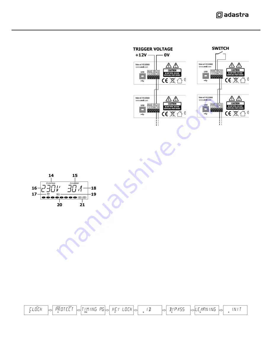
Remote Operation 


The DP-8 has 4 screw terminals to allow global 
control of the power schedule using a switch or 12V 

remote trigger.  
 

Connecting a switch across the +12V and REM IN 
terminals will operate as a global ON/OFF switch for 

the DP-8. 
 

When the switch is closed, the power schedule will 
switch on and off as programmed. When the switch 

is open, the power schedule will be disabled. 
 

Likewise, an external 12V trigger can be used by 
conn12V to to REM IN and 0V to GND. 

 
Further DP-8 units can be controlled in tandem by 

connecting STATUS of a switched DP-8 to the REM 
IN of another DP-8. 
 

For this operation, both GND terminals will need to 
be connected.  


Powering up 


When all connections are made, with 

the main circuit breaker (1) in the “OFF” position, 

connect power to the DP-8. 

Switch the power supply on and power up the DP-8 by switching the 

main circuit breaker to the “ON” position.


Display Layout 


The DP-8 display is multi-functional, showing the status during normal operation and parameter values in the settings menu. 

 
During initial power-

up, there is a scrolling “ADASTRA” greeting and then the display shows the mains voltage and current values.


The display is backlit, which dims after approximately 40 seconds if there are no buttons pressed. 
 

The 8 output channels can be operated manually by switching any of the front panel buttons (6) on or off. 
(this will not be effective if any channels are set to be always on as detailed in the Bypass setting section) 

 
Press and hold the Settings/Display button (2) to change the display to the current time & day. 
 

Press and hold again to revert the display to mains voltage and combined current draw through the 8 outputs. 
 

If the panel is locked, the display will 

show “CODE” and the key code will need to be entered before the panel will functi

on (see below) 

A short press of the Settings/Display button enters the settings menu as described below. 

 
Settings menu 

 
Press the Settings/Display button (2) to enter the Settings menu and step through the different options using the < and > buttons (7), 

which also serve as numerical buttons 7 & 8. Press the Enter button (3) to select a parameter to set. 


Pressing the ESC button (4) will escape the settings menu and revert to the normal operation display (i.e. not settings menu) 


14 

Voltage alarm indicator 

15 

Current alarm indicator 

16 

Mains voltage display 

17 

Timer schedule active indicator 

18 

Mains output current display 

19 

Day indicator for timer schedule 

20 

IEC outputs active indicators 

21 

On & Off indicators 

Содержание DP-8

Страница 1: ...DP 8 DIGITAL POWER SCHEDULE CONTROLLER Item ref 953 058UK User Manual Version 1 0 ...

Страница 2: ...ower from mains during stormy weather or if unused for long periods 11 In case of malfunction water ingress or other damage consult qualified service personnel 12 Do not place in damp areas or near liquids or moisture Do not spill liquids on the housing 13 Please pay attention to warning symbols during transit and placement 14 Terminals marked with the symbol are HAZARDOUS LIVE and should only be ...

Страница 3: ... sure that the total current load will not exceed the fuse or breaker if all IEC outputs are activated at the same time If more than one single appliance is to be powered from any of the IEC outlets a splitter or distribution block may be used so long as the combined load on the individual IEC outlet is less than 10A For very high power configurations any of the IEC outputs can be used to remotely...

Страница 4: ...ge and current values The display is backlit which dims after approximately 40 seconds if there are no buttons pressed The 8 output channels can be operated manually by switching any of the front panel buttons 6 on or off this will not be effective if any channels are set to be always on as detailed in the Bypass setting section Press and hold the Settings Display button 2 to change the display to...

Страница 5: ...m value it cannot be saved Once the values are set press the Enter button to save the settings or ESC to exit without saving Note if the current exceeds 32A or if there is a short circuit the main circuit breaker will trip Timing program The DP 8 timing program enables the installer to program a schedule for one or more of the IEC outputs to be switched on or off There are 99 internal events which...

Страница 6: ...hen press Enter Set the ID number using the buttons 8 and press Enter again to confirm Bypass The Bypass setting enables the user to select which channels are set to always on bypassing manual or timer control From the settings menu step through the options until BYPASS is displayed and then press Enter Set the channel buttons 6 on for channels which are to be always on regardless of timer or manu...

Страница 7: ...outlets Connections USB port RS485 12Vdc out remote GND Status Dimensions 482 x 250 x 44mm Weight 3 0kg Disposal The Crossed Wheelie Bin symbol on the product means that the product is classed as Electrical or Electronic equipment and should not be disposed with other household or commercial waste at the end of its useful life The goods must be disposed of according to your local council guideline...

Отзывы: