background image

                                                       Adaptive® JUNIOR – Technical and HMI User Guide 


REV 1.04 


12


4.


Using the Software 

4.1.


Starting the Software and Connecting the Controller 

The JUNIOR has RS232 and USB ports, either of which can be used to connect the JUNIOR to a PC for configuration 
and control. If using the USB serial port, a USB cable must be plugged in and the JUNIOR powered on 

before

 the HMI 

is started, so that it detects the USB port. If using the RS232 serial port simply connect it to the PC. If the PC does not 
have a free serial port, a USB to serial port adapter can be used instead. Whichever port is chosen, if it is not visible 
in the drop-down list double check the connection and power, and if using either of the USB types verify that the 
correct USB drivers have been loaded.  

To start the HMI, double click on the Adaptive HMI shortcut icon  

  or select it from the start menu 

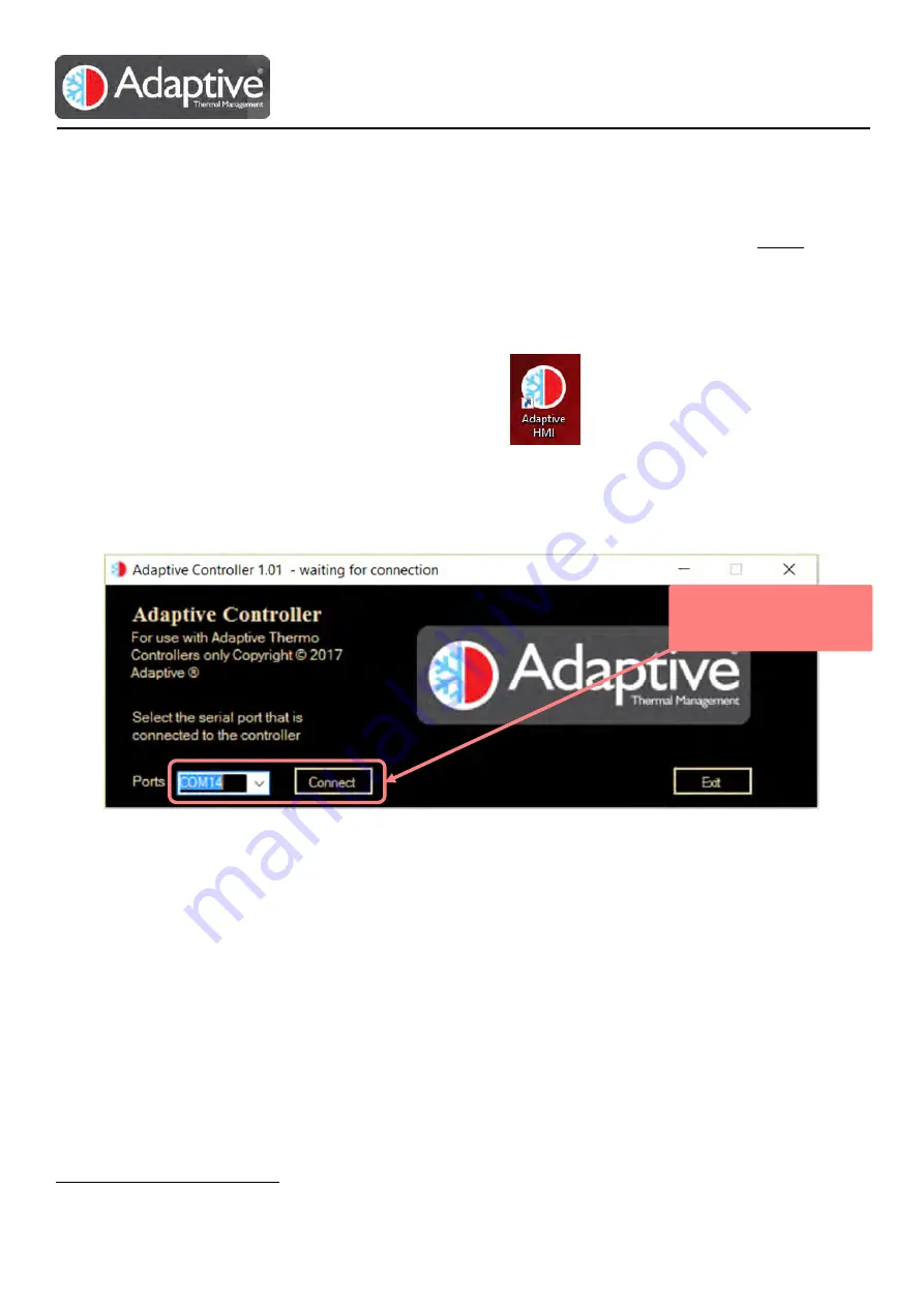
Adaptive group. This will bring up the connection window where the serial port being used can be selected. Select 
the port from the available port list and click the connect button. On successful connection the main display will 
appear otherwise a communication error message will be displayed if there are problems talking to the unit. If so 
double check the connection cable, power and that you have selected the correct port connected to the JUNIOR. 


Figure 8 HMI connection screen 

4.2.


Software Flow 

The HMI software provides four main options depending on the product that it is connected to; 1 live monitoring of 
the variables and alarm status, 2 configuration of the alarm limits and enables, 3 selection of the control mode 4 and 
configuration / calibration of the connected temperature sensors and fans

1

. A plotting page is also provided to view 

trends and allow logging to file. 

The menu section of the display is arranged so that the most frequently used pages are shown at the top and lesser 
used below. When configuring a device for the first time the menu is normally worked in reverse upwards as the 
configuration of the sensors should be completed before attempting to use the device in an operational mode. The 
menu items vary according to the product connected but the Alarm Status button will always be topmost, see Figure 
6

Error! Reference source not found.

. Whenever an active alarm is present in the system and the Alarm Status page 

is not on display, its button will flash to indicate the presence of an alarm which the user should investigate. 

When the HMI successfully connects to a device the Alarm Status page is automatically displayed. 


1

 Options depend on product being used e.g. Fans available on JUNIOR 

Select the port being 

used and click connect 

Содержание JUNIOR

Страница 1: ...Adaptive JUNIOR Technical and HMI User Guide REV 1 04 1 JUNIOR User Guide Version 1 04 09th Jan 2019 ...

Страница 2: ... HMI Display 11 4 Using the Software 12 4 1 Starting the Software and Connecting the Controller 12 4 2 Software Flow 12 4 3 Alarm Configuration Pages 13 4 3 1 Temperature Sensor Alarm Configuration Page 13 4 3 2 Fan Alarm Configuration Page 14 4 4 Alarm Status Page 15 4 5 Control Page 16 4 5 1 Manual Control Mode 16 4 5 2 Thermostat Control Mode 17 4 5 3 PID Control Mode 18 4 5 4 PID Auto Tune Mod...

Страница 3: ...d RS232 connection allowing direct interface to a PC for easy programming and evaluation Users can download the latest version of the Adaptive HMI control software to configure and monitor applications using the JUNIOR board The board features include RS232 and USB programming interface Four thermocouple or NTC sensor inputs Two operating mode feedback LEDs Manual set temperature Three fan driver ...

Страница 4: ...lay to monitor parameters in offline mode 11 Service mode Special boot mode activated if jumper fitted eg Firmware upgrade 12 Fan 1 direct power Fan 1 directly powered from the power input connector if jumper fitted 13 Fan 2 direct power Fan 2 directly powered from the power input connector if jumper fitted 14 Fan 3 direct power Fan 3 directly powered from the power input connector if jumper fitte...

Страница 5: ...hermoelectric system To keep potential interference problems to a minimum ensure that the wires used for connecting the power supply to the controller and especially from the controller to the thermoelectric assembly TE OUT and TE OUT are sized correctly for the module s power and kept as short as possible Wire lengths can be optimised by mounting the JUNIOR controller right at the thermoelectric ...

Страница 6: ...Adaptive JUNIOR Technical and HMI User Guide REV 1 04 6 Figure 3b Wiring diagram of complete installation Figure 3c Wiring diagram for Thermoelectric Assemblies with thermal protection ...

Страница 7: ...o 3 negative 0 0 001 J1 7 SENS D or 4 Input Sensor No 4 positive 3 3 0 001 J1 8 SENS D or 4 Input Sensor No 4 negative 0 0 001 J2 1 Fan 1 or A GND Output Fan 1 power negative 0 2 J2 2 Fan 1 or A PWR Output Fan 1 power positive 48 2 J2 3 Fan 1 or A TACH Input Fan 1 TACH signal 3 6 0 01 J2 4 Fan 1 or A PWM Output Fan 1 PWM signal 3 6 0 01 J2 5 Fan 2 or B GND Output Fan 2 power negative 0 2 J2 6 Fan ...

Страница 8: ...the user to access on the board Each channel can be used to drive a hot or cold side fan on a thermoelectric assembly Speed monitoring or control also supported for three and four wire fans Signals TACH and PWM are internally pulled up to 3 3V DC and care should be taken selecting a suitable fan 1 7 Alarm Interface An isolated relay is available for user applications requiring alarm signalling In ...

Страница 9: ...andard serial protocol detailed within this document 1 12 Mechanical Dimensions Figure 5 Mechanical Dimensions Height and clearance information is shown in Table 5 Component height on the bottom side 3mm PCB substrate thickness 1 6mm Component height on the top side 22mm Total height 26 6mm Recommended minimum clearance around the board 5mm SD card protrusion 1 5mm Micro USB connector protrusion 1...

Страница 10: ...r account Locate the installation package unzip if necessary to a temporary location and run the setup exe installation file Follow the on screen instructions provided note if the Microsoft Net version needs to be upgraded you will be prompted to download or obtain it before continuing Once installed a new Adaptive HMI icon will be placed on the desktop and in the All Programs menu 2 4 JUNIOR Quic...

Страница 11: ...his shows the current values of the device such as temperature drive voltage and current mode and status This is typically updated every second Menu Buttons These buttons select the various configuration and alarm pages available for the device The number and type will vary according to the device that is connected Configuration This area shows the available configuration or alarm parameters that ...

Страница 12: ...he connection cable power and that you have selected the correct port connected to the JUNIOR Figure 8 HMI connection screen 4 2 Software Flow The HMI software provides four main options depending on the product that it is connected to 1 live monitoring of the variables and alarm status 2 configuration of the alarm limits and enables 3 selection of the control mode 4 and configuration calibration ...

Страница 13: ... datasheet 4 3 1 Temperature Sensor Alarm Configuration Page Two configurable alarms are available for each temperature sensor detailed below Up to four sensors can be connected and the alarms individually configured using the A B C or D sensor selection buttons at the top right of the configuration page see Figure 9 below Note the alarms only operate if a sensor is enabled on its configuration pa...

Страница 14: ...Settings Alarm Type Description Cause Current mA Sets maximum fan current limit Alarm trips when the measured current exceeds this value Voltage V Sets maximum fan voltage limit Alarm trips when the measured voltage exceeds this value Speed High RPM Sets the upper rotational speed limit Alarm trips if the fan speed rises above this value2 Speed Low RPM Sets the lower rotational speed limit Alarm t...

Страница 15: ... Alarm status page Alarm Status 3 Alarms are only valid for the sensors or fans that are connected and enabled Alarm Type Alarm Status Description Cause Latched Alarms Shutdown Active At least one alarm with shutdown option selected has tripped or Internal fault has occurred Fault Active Indicates an internal fault has occurred Temperature Sensors Sensor A Sensor B Sensor C Sensor D Low The measur...

Страница 16: ...tput The output mode is only selectable when the controller is in the Off mode Care should be taken to ensure that the connected device is compatible with the selected output drive method Note Off mode is also used for clearing shutdown alarms 4 5 1 Manual Control Mode This is an open loop mode that allows the user to set the drive output at a fixed value of its maximum The temperature sensor conn...

Страница 17: ... a problem in modern systems but energy and switching are still important Dead band is similar to hysteresis but where hysteresis is used to prevent the output switching unnecessarily dead band switches off the output completely while the temperature is within its window The switching on point for the heater is setpoint dead band hysteresis and for switching on the cooler setpoint dead band hyster...

Страница 18: ...rmed to quickly provide a usable set that can later be tuned and optimised for the expected operating conditions Warning The auto tune process will provide full positive and negative step outputs so the connected system must be able to handle the maximum drive levels safely and without causing damage The time taken to perform the auto tune varies with each system but is normally 5 to 10 minutes ho...

Страница 19: ...ually cause the system to oscillate as the output is driven strongly on the small errors Proportional control will give output that will overshoot the setpoint and always remain short of the desired temperature It is not suited to situations that have large variations in the load The I Integral term is used to reduce the remaining error left by the P term It does this by accumulating the error ove...

Страница 20: ...before plotting resumes with the new items If the items are changed whilst logging to a file is in progress the logging simply carries forward with the new items being logged causing a discontinuity in the log file The display options settings affect how the scope data is displayed this no effect on logging Display Option Effect Show Scope Displays the scope in a window below the main application ...

Страница 21: ... achieved by clicking on the log button and entering a file name The data is recorded in a comma separated format which if the file name ends with the extension csv can easily be opened in Microsoft Excel When logging is in progress the button changes to Stop logging Figure 21 Sample log file showing CSV data format ...

Страница 22: ...3 are removed any that are fitted will cause that particular fan to be supplied from the input and then select the required supply voltage of 5V 12V or 24V from the fan voltage option drop down list Note When using the programmable PSU the supply voltage should be above the selected fan voltage to ensure correct regulation of the fan supply Use the instruction list below to configure each fan that...

Страница 23: ...s not provide the A B and C constants required for the configuration they can be calculated by using freely available NTC coefficient calculators These take three temperature resistance pairs from the datasheet and produce the A B and C coefficients choose temperatures at the extremes of the expected operating conditions for the unit to achieve the best accuracy when the temperature is converted N...

Страница 24: ...ed The calibration can also be used to minimise errors when a temperature offset exists such as when the temperature sensor is not located close to the energy source The gain and offset values are used to apply a straight line adjustment to the temperature measurement The values are typically calculated by taking two measurements of both the indicated temperature on the controller and that from a ...

Страница 25: ...s are not accepted and will return an Error_6 unexpected data command that was used Some example commands are shown below note the and are not part of the command and are not typed Command Result Description ID cr lf ID Junior Temperature Controller V1 01 ETDYN c Nov 27 2017 cr lf Reads the identification REG 1 cr lf REG 1 320 cr lf Reads the status register REG 4 25 cr lf REG 4 25 0000 cr lf Writ...

Страница 26: ... to 100000 0 Steinhart Coefficient x for sensor A 18 A 19 B 20 C Floating point 100000 0 to 100000 0 Steinhart Coefficient x for sensor B 21 A 22 B 23 C Floating point 100000 0 to 100000 0 Steinhart Coefficient x for sensor C 24 A 25 B 26 C Floating point 100000 0 to 100000 0 Steinhart Coefficient x for sensor D 27 A 29 B 31 C 33 D Integer 1000 to 1000 C Temperature alarm low limit for sensor x 28...

Страница 27: ...3 Floating point Read only Supply voltage value 84 Floating point Read only On board potentiometer reading 90 A 92 B 94 C 96 D Floating point Calibration gain for sensor x 91 A 93 B 95 C 97 D Floating point Calibration offset for sensor x Table 7 Status bit details Bit 1 indicates condition is active Table 8 Bit arrangement for alarm enable relay and shutdown registers Sensor Sensor D Sensor C Sen...

Страница 28: ...gments an active alarm will only cause the relay or shutdown to become active if the associated bit has been set in the enable segment Table 11 Fan alarm status bits Type Shutdown Relay Alarm Alarm low speed high speed over voltage over current low speed high speed over voltage over current low speed high speed over voltage over current Bit number 11 10 9 8 7 6 5 4 3 2 1 1 Bit 1 indicates alarm co...

Отзывы: