


2-19
About the DuraStor Storage Subsystem
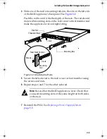
Disk I/O Card
The disk I/O card of the DuraStor 312R (see
Figure 2-20
) connects
the host computer (server) to the storage enclosure’s disk drives
and to other DuraStor 312R storage enclosures.
Warning:
The disk I/O card is
not hot-swappable
. You must
turn off the power to the DuraStor 312R to replace this
card. See
Powering Off
on page 3-54
.
Figure 2-20. DuraStor 312R Disk I/O Card
Located on the disk I/O card are two 68-pin very-high-density
SCSI connectors. These connectors are labeled Channel 1 (Input)
and Channel 2 (Output).
Note:
The DuraStor 312R does not support High Voltage
Differential (HVD) SCSI.
Also located on the disk I/O card are three sets of jumpers. Two of
the jumpers, JP1 and JP3, route termination power to the SCSI bus.
The default setting is
jumpered
(a jumper on both pins).
The third jumper, JP2, enables or disables automatic termination.
The default setting is
unjumpered
(the jumper offset—removed from
one pin). This default setting means that termination is automatic,
so that when a data cable is plugged in, the system automatically
senses the connection’s ground and provides the required SCSI
termination. No external termination is required.
CHANNEL 2
(OUTPUT)
CHANNEL
1
(INPUT)
DISK I/O
CHANNEL 2
ADD JUMPER
TO SUPPL
Y
TERMINA
TION PO
WER
CHANNEL
1
ADD J
UMPE
R TO SUPPL
Y
TERMINA
TION PO
WER
JP1
JP2
JP3
ADD JUMPER
TO
DISABLE TE
RMINA
TION
JP2
Channel 2
(JP1)
Channel 1 (JP3)
DuraStor IUG.book Page 19 Wednesday, January 30, 2002 10:49 AM


