7
TECHNICAL INSTRUCTION
intended for the installer
The fryer must be connected to the gas installation only by an authorized installer.
1. SUBASSEMBLIES DESCRIPTION
The pressure gas fryer is composed of the following sub assemblies:
Gas installation
The fryer can be connected to the B/P active gas installation through the gas reducing valve for
36 mbar or natural E gas (GZ50) and therefore it will be equipped ( consistently with the
order)with a proper gas connector pipe:
- with a crimped terminal for a liquefied petroleum gas installation used with the liquefied
petroleum gas GPB elastic hose.
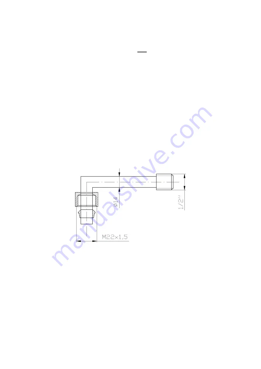
- with an external thread Rc ½ for the natural gas E ( GZ 50) ( according to the picture below)
The control/cut off valve Minisit 710 connected with a thermoelectromagnetic dust-proof
protection of the handset's burner,
Gas installation pipes.
External thread Rc ½ for the natural gas E
2.
THE FRYER ASSEMBLY
The room where the fryer is mounted should correspond to the building laws included in the order
of Minister of Infrastructure from 12.04.2002 concerned with the technical standards buildings
and their layouts should meet.
According to those standards such room should have:
a working supply-exhaust ventilation providing continuous air circulation, at least 37,5 m³/h
for each kilowatt of the gas device's thermal power.
The minimal dimension of the smoke conduit must not be smaller than 0,14 m , and the total
surface of the ventilating hood must not be smaller than 0,016 m²
Proper cubic capacity which provides that maximum heat coming from the gas devices will not
Содержание ADA SCG 11
Страница 15: ...15...


