CBE25
Manuale tecnico – Technical manual
Code
MT-CBE25-02021080-R00
Page 05/16
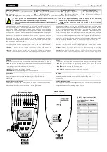
Il dispositivo può pilotare svariati tipi di valvola o in alternativa una resistenza o un
compressore. I morsetti 7 e 8 sono relativi all’uscita caldo mentre i morsetti 9 e 10 sono
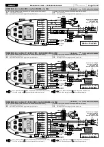
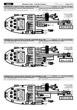
relativi all’uscita freddo. In Fig. 1 sono visibili diverse modalità di collegamento delle
valvole a seconda del loro tipo.
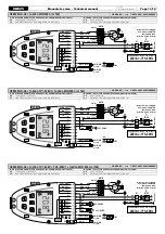
Agendo sulla configurazione si sceglie quale tipo di valvole si intende usare:
Nel caso si usino valvole on-off o on-off PWM proporzionali, collegare secondo
CBE25-
A002
o
CBE25-A003
. Nel caso si usino servocomandi flottanti a tre punti, collegare
secondo
CBE25-A007
o
CBE25-A008
.
E’ possibile gestire impianti con tipi di valvole diversi per caldo e freddo.
Nel caso l’impianto preveda una resistenza elettrica di integrazione oppure al posto
della valvola caldo, collegare come da schemi
CBE25-A005
o
CBE25-A006.
Terminals 7 and 8 are for the heating output, while terminals 9 and 10 are for the
cooling output. Fig. 1 shows different valve connection modes, according to their
type.
Change configuration to select which type of valve is used:
If on-off or proportional PWM on-off valves are used, connect according to
CBE25-
A002
or
CBE25-A003
. If 3 point floating servocontrols are used, connect according to
CBE25-A007
or
CBE25-A008
.
Systems with different types of valves on heating and cooling outputs can be
managed.
If the system has an electric heater for integration or in replacement of the heating
valve, connect according to diagrams in
CBE25-A005
or
CBE25-A006.
Il termostato può gestire anche un impianto pompa di calore e quindi pilotare il
compressore e la valvola di inversione a quattro vie. La valvola di inversione va
collegata su un morsetto diverso a seconda della sua logica di funzionamento.
The thermostat can also manage a heat pump system and, therefore, control the
compressor and a 4-way change-over valve. The change-over valve is connected to
a different terminal to get a reverse operation logic.
CARATTERISTICHE TECNICHE
TECHNICAL FEATURES
Alimentazione
230V~ -15% +10% 50Hz
oppure 230V~ ±10% 60Hz
oppure 24V~ -15% +10% 50/60Hz
Power supply
230V~ -15% +10% 50Hz
Or 230V~ ±10% 60Hz
Or 24V~ -15% +10% 50/60Hz
Potenza assorbita
1,2VA
Power absorption
1.2VA
Temperatura aria ambiente (SND-A4, standard)
-
Campo di regolazione
-
Tipo di sensore
-
Precisione
-
Risoluzione
-
Campo di visualizzazione
-
Isteresi
5°C .. 35°C (configurabile)
NTC 10kΩ @ 25°C ±1%
± 1°C
0,1°C
-10°C ... +50°C
Regolabile 0,2 .. 1,0 °C
Room temperature (SND-A4, standard)
-
Regulation range
-
Sensor type
-
Precision
-
Resolution
-
Display temp. range
-
Differential
5.0 .. 35.0 °C (configurable)
NTC 10kΩ @ 25°C ±1%
± 1.0 °C
0.1 °C
-10°C .. +50°C
adjustable 0.2 .. 1.0 °C
Temperatura acqua mandata (SND-W4, opzionale)
-
Tipo di sensore
-
Precisione
-
Risoluzione
-
Campo visualizzazione
-
Isteresi
NTC 10kΩ @ 25°C ±1%
± 1 °C
1 °C
0°C .. 99 °C
2°C
Supply pipe temperature (SND-W4, optional)
-
Sensor type
-
Precision
-
Resolution
-
Display temp. range
-
Differential
NTC 10kΩ @ 25°C ±1%
± 1 °C
1 °C
0 .. 99 °C
2 °C
Portata contatti
-
Ventilatore
-
Valvole
-
Valvole (in caso di carico induttivo)
3A @ 230V~ cosφ=1
0,3A @ 230V~ cosφ=1
10VA Max potenza pilotabile
Contact rating
-
Fan motor
-
Valves
-
Valves (inductive load)
3A @ 230V~ cosφ=1
0.3A @ 230V~ cosφ=1
10VA Max load power
Grado di protezione
Tipo di azione
Categoria di sovratensione
IP 20
1
II
Protection grade
Type of action
Overvoltage category
IP 20
1
II
Grado di inquinamento
Indice di tracking (PTI)
Classe di protezione contro le scosse elettriche
Tensione impulsiva nominale
Numero di cicli manuali
Numero di cicli automatici
2
175
II ( )
2500V
50000
100000
Pollution degree
Tracking Index (PTI)
Class of protection against electric shock
Rated impulse voltage
Number of manual cycles
Number of automatic cycles
2
175
II ( )
2500V
50000
100000
Classe del software
A
Software class
A
Tensione prove EMC
Corrente prove EMC
esclusione modo guasto ‘corto’
Temperatura prova sfera
230V~ 50Hz
31mA
Tolleranza distanze ±0,15mm
75 °C
EMC test voltage
EMC test current
Distances tolerances fault mode ‘short’ exclusion
Ball pressure test temperature
230V~ 50Hz
31mA
±0,15mm
75 °C
Temperatura di funzionamento
Temperatura di stoccaggio
Limiti di umidità
0°C .. 40°C
-10°C .. +50°C
20% .. 80% RH (non condensante)
Operating temperature
Storage temperature
Humidity limits
0 .. 40 °C
-10°C ... +50 °C
20% ... 80% RH (non condensing
Contenitore
-
Materiale
-
Colore
ABS + PC, V0 autoestinguente
Bianco segnale (simile RAL9003)
Case
-
Material
-
Color
ABS + PC, V0 self-extinguishing
Signal white (RAL 9003)
Classificazione Secondo Regolamento 2013.811.CE
-
Classe
-
Contributo all’efficienza energetica
V
3%
Classification under reg. 2013.811.EC
-
Class
-
Contribution to energy efficiency
V
3%
GARANZIA
WARRANTY
Nell’ottica di un continuo sviluppo dei propri prodotti, il costruttore si riserva il diritto di
apportare modifiche a dati tecnici e prestazioni senza preavviso. Il consumatore è
garantito contro i difetti di conformità del prodotto secondo la Direttiva Europea
1999/44/c nonché il documento sulla politica di garanzia del costruttore. Su richiesta è
disponibile presso il costruttore il testo completo della garanzia.
In the view of a constant development of their products, the manufacturer reserves
the right for changing technical data and features without prior notice. The consumer
is guaranteed against any lack of conformity according to the European Directive
1999/44/EC as well as to the manufacturer’s document about the warranty policy. The
full text of warranty is available on request from the manufacturer.
APPENDICE
APPENDIX
SELEZIONE RISCALDAMENTO/RAFFRESCAMENTO
La selezione del modo raffrescamento (estate) o riscaldamento (inverno), avviene
tenendo premuto per alcuni secondi il pulsante menù fino a che il display non
visualizzi una delle seguenti scritte indicanti lo stato attualmente impostato:
Modo riscaldamento (inverno)
Modo raffrescamento (estate)
Successivamente, premendo il pulsante o o , si cambia l’impostazione
ciclando tra riscaldamento e raffrescamento.
Premendo gli altri pulsanti si esce dal menù di selezione memorizzando la scelta effettuata.
In caso di termostato configurato per una selezione raffrescamento/riscaldamento
automatica
o
centralizzata
non
è
possibile
modificare
la
selezione
riscaldamento/raffrescamento ed il display visualizza l’icona lampeggiante.
HEATING/COOLING SELECTION
Heating or cooling modes are selected by keeping the “menu“ button depressed
for some seconds, until the display shows one of the following texts which indicates the
current mode:
Heating mode
Cooling mode
Then, by pressing the or or , the user can change the desired mode,
cycling between heating and cooling. Depressing any of the other buttons results in
saving the choice and quitting the menu.
When the thermostat is configured for automatic or centralised heating/cooling
selection, the selection cannot be manually changed and if tried, the display shows
the flashing icon.
INGRESSO TEMPERATURA ACQUA DI MANDATA
Il dispositivo prevede un ingresso per la sonda della temperatura di mandata
dell’acqua (SND-W4): quando quest’ultima viene utilizzata il termostato può
automaticamente determinare se sia impostato in modo “raffrescamento”, quindi si
debba raffreddare o sia in modo “riscaldamento” e quindi riscaldare: in pratica il
dispositivo effettua la funzione di “changeover” automatico in base alla temperatura
dell’acqua. Questa rilevazione viene anche utilizzata per realizzare la funzione
“termostato di minima”.
In alternativa alla sonda di mandata sullo stesso ingresso si può collegare un
termostato bimetallico (TM-32, TM-42) per realizzare la funzione “termostato di minima”.
DELIVERY WATER SENSOR
This controller features an input for the delivery water temperature sensor (SND-W4):
when this sensor is installed the controller can automatically understand whether it
should be working in “cooling“ mode or in “heating“ mode: this function is called
“water temperature changeover”. The water temperature is also used to perform the
“cut-off thermostat“ function.
Alternatively a bimetallic thermostat (TM-32, TM-42) can be wired to the input to get
the “cut-off“ function.
INGRESSI ESTERNI - piazzole M13/EI, M14/RDC-ECO e M15-M16/CF
Il termostato dispone di tre ingressi esterni a cui è possibile associare funzioni diverse
tramite i parametri
C14
,
C15
e
C16
.
I segnali alle piazzole M13/EI e M14/RDC-ECO possono essere collegati alle piazzole
M13/EI e M14/RDC-ECO di altri termostati presenti nello stesso edificio per realizzare
funzioni centralizzate.
EXTERNAL INPUTS -
pitches
M13/EI, M14/RDC-ECO and M15-M16/CF
The thermostat has three external inputs that can be associated to different functions
through parameters
C14
,
C15
and
C16
.
Signals to terminals
pitches
M13/EI and M14/RDC-ECO can be connected to
pitches
M13/EI and M14/RDC-ECO of other thermostats in the same building for centralised
functions.
Содержание CBE25
Страница 18: ......


