CBE25
Manuale tecnico – Technical manual
Code
MT-CBE25-02021080-R00
Page 06/16
Il segnale alle piazzole M15/CF, M16/COM-CF non può essere collegato ad altri termostati.
Le funzioni che è possibile associare agli ingressi sono:
Funzione “Estate/Inverno centralizzata“
In un’installazione in cui siano presenti più termostati in uno stesso edificio, l’ingresso
centralizzato di ogni termostato può essere collegato insieme e pilotato dalla centrale
termica. In questo modo la centrale termica decide se i termostati devono regolare in
modo riscaldamento o raffrescamento.
Funzione “Economy“
L’ingresso può attivare/disattivare il modo economy (vedere paragrafo “Funzione
economy”). A questa funzione è possibile associare la seguente icona:
Il termostato è sensibile al cambiamento di stato dell’ingresso e non al livello e quindi
è sempre possibile, tramite il pulsante (se abilitato), cambiare lo stato economy
del termostato.
Funzione “Stop regolazione“
L’ingresso può sospendere o riattivare la regolazione della temperatura ambiente.
Quando la regolazione è sospesa il ventilatore rimane spento, le valvole rimangono
chiuse ed i relativi simboli sul display lampeggeranno.
A questa funzione è possibile associare una delle seguenti icone: o o
Configurando un ingresso con la funzione “stop regolazione” con l’icona si realizza
la funzione “contatto finestra”. Collegando all’ingresso un contatto finestra, quando
la finestra è aperta si accenderà l’icona sul display e la regolazione della
temperatura ambiente sarà sospesa.
Nota
: ci sono delle limitazioni per l’uso del
contato finestra, leggere attentamente il paragrafo “ATTENZIONE”.
The signal on pitches M15/CF, M16/COM-CF cannot be connected to other thermostats.
Functions that can be associated to the inputs are:
“Centralised Heating/Cooling“ function
When installations have multiple thermostats in a single building, the centralised inputs
of each thermostat can be connected together and controlled by the central
heating room. This way the central heating room determines whether the thermostats
must operate in the heating or cooling mode.
“Economy“ function
The input activates/deactivates the economy mode (see the “Economy function“
paragraph). This function can be associated with the following icon:
The thermostat is sensitive to the input status changes and not to the level, so it is
always possible to change the economy status with the button (if enabled).
“Regulation stop“ function
The input can suspend or reactivate room temperature regulation. When temperature
regulation is suspended the fan is stopped, the valves remain closed and the relevant
symbols on the display will flash.
This function can be associated with one of these icons: or or
When an input is configured for the “regulation stop” function and the icon, the
“window contact” function is performed. Connecting a window contact to the input,
when the window is open the icon will appear on the display and the
temperature regulation will be suspended.
Note
: there are limitations for window contact use. Carefully read the paragraph
“ATTENTION”.
Funzione “ON/OFF termostato”
L’ingresso accende o spegne il termostato come se si fosse premuto il pulsante
Il termostato è sensibile al cambiamento di stato dell’ingresso e non al livello e quindi
è sempre possibile, tramite il pulsante (se abilitato), cambiare lo stato
acceso/spento del termostato.
“Thermostat ON/OFF” function
The input turns the thermostat on or off, like pressing the button.
Since the thermostat is sensitive to input status changes and not to the level, so it is
always possible to change the on/off status with the button (if enabled).
Funzione “allarme motore”
L’ingresso accende l’icona sul display.
Quando l’allarme è attivo viene interdetta l’eventuale uscita resistenza.
“Motor alarm” function
The input lights the icon on the display.
When the alarm is active, the electric heater output will be cut off.
Funzione “Allarme resistenza”
Quando l’allarme è attivo, sul display lampeggiano i simboli + e viene
interdetta l’eventuale uscita resistenza.
A questo ingresso si può collegare il temostato di sicurezza della resistenza.
“Electric heater alarm” function
When the alarm is activated + symbols flash on the display and the electric
heater output will be cut off.
The electric heater safety thermostat can be connected to this input.
Funzione “Avviso filtro sporco”
L’ingresso attiva l’avviso di filtro sporco, sul display lampeggia l’icona filtro
“Dirty filter” warning function
the input activate the dirty filter warning, the filter icon blinks on the display.
ACQUISIZIONE TEMPERATURE
Il termostato acquisisce la temperatura ambiente e la temperatura dell’acqua di
mandata nella batteria del fan-coil tramite sonde del tipo NTC. La temperatura
ambiente viene acquisita e visualizzata con risoluzione descritta precedentemente
nel range -10°C...+50°C.
Nel caso la temperatura ambiente sia al di fuori del range operativo, il display
visualizza la scritta “
Or
” (out of range). Se la sonda è interrotta oppure in corto
circuito,
il display mostra la scritta “
EEE
” (errore): la regolazione del termostato non è
più effettuabile e tutte le uscite restano disattivate.
La temperatura ambiente viene sempre acquisita dalla sonda esterna
“SND-A4” collegata al connettore RS (SA).
Il parametro
P10
della "configurazione installatore" rimane sempre a “1” per
selezionare la sonda esterna e non è possibile modificarlo.
La temperatura dell’acqua di mandata nella batteria del fan-coil viene rilevata da una sonda
esterna (SND-W4) e può essere visualizzata con risoluzione di un grado nel range 0°C...99°C.
Nel caso la temperatura rilevata sia al di fuori del range operativo, quando si tenta di
visualizzarla il display mostra la scritta “
Or
” (out of range). Se la sonda è interrotta
oppure in corto circuito il display mostra la scritta “
EEE
” (errore) e le funzioni legate a
questa informazione non vengono eseguite.
La sonda di mandata può non essere collegata se l’impianto non la richiede. Per
l’attivazione della funzione relativa alla sonda di mandata, fare riferimento a quanto
descritto nel paragrafo “Funzione termostato di minima”.
TEMPERATURE ACQUISITION
This controller acquires both the room temperature and the delivery water
temperature in the fan-coil exchanger with NTC type sensors.
The room temperature is acquired and displayed with the above mentioned
resolution in the range -10°C...+50°C.
The room temperature is always acquired by the “SND-A4” external sensor wired to
the RS (SA) connector.
The parameter
P10
in the ‘installer configuration’ is always set at “1” to select an
external sensor, and it cannot be modified.
The supply water temperature in the fan-coil is acquired through a remote sensor
(SND-W4) and can be displayed with 1°C resolution in the 0°C…99°C range. The
delivery water sensor does not have to be installed in case the system does not
require it. To enable delivery water sensor related functions, see the “Cut-off
temperature function“ section.
In case the room or water temperature falls outside the operating range, the display
shows “
Or
“ (out of range). In case the sensor is faulty as an open or a short circuit, the
display shows “
EEE
“ (error): in this situation, functions which need the temperature are
n
o
t performed.
FUNZIONE TERMOSTATO DI MINIMA
La funzione termostato di minima permette di interdire il funzionamento del ventilatore
quando, in modalità riscaldamento, l’acqua di mandata non sia sufficientemente
calda. Per impostare questa funzione è necessario collegare una sonda di mandata
(SND-W4) o, in alternativa e sugli stessi morsetti, un termostato bimetallico (TM-32, TM-42).
Nel caso si usi la sonda (SND-W4), la soglia a cui si discriminerà tra acqua
sufficientemente calda o no è definita dal parametro
P22
. Nel caso non si desideri
questa funzione si può impostare per il parametro
P22
una soglia molto bassa (0).
Nel caso invece si voglia usare un termostato bimetallico (TM-32, TM-42) per questa
funzione, è necessario impostare il parametro
P07
sul valore 2, quindi il ventilatore sarà
abilitato solo quando il contatto bimetallico sarà chiuso. Utilizzando quest’ultima
opzione non è possibile né visualizzare la temperatura di mandata né realizzare la
funzione di changeover automatica.
Per l’impostazione dei parametri riguardanti le funzioni di cui sopra, fare riferimento a
quanto descritto nel paragrafo “Configurazione installatore”.
La funzione “termostato di minima” è disponibile anche in modo raffrescamento, in
questo caso il ventilatore verrà interdetto quando l’acqua di mandata non è
sufficientemente fredda secondo la soglia definita dal parametro
P23
. Nel caso non si
desideri questa funzione si può impostare un valore molto alto sul parametro
P23
(99).
Quando la temperatura dell’acqua di mandata non è sufficientemente calda o
fredda secondo le soglie
P22
e
P23
, il display visualizza l’icona , il ventilatore
rimane spento e i simboli “velocità ventilatore” lampeggiano.
CUT-OFF TEMPERATURE FUNCTION
The cutoff temperature function is used to inhibit the fan operation whenever, in
heating mode, the delivery water is not hot enough. In order to accomplish this
function a delivery water sensor (SND-W4) must be wired, alternatively, a bimetallic
thermostat (TM-32, TM-42) can be wired to the same terminals. In case the delivery
water sensor (SND-W4) is used, the “water hot enough” threshold is defined on
parameter
P22
. In case this function is not needed, parameter
P22
can be set to a
very low value (0).
In case a bimetallic thermostat (TM-32, TM-42) is used for this function, parameter
P07
must be set to the value 2: in this case the fan operation will be enabled only when
the bimetallic contact is closed.
When this type of bimetallic thermostat is used the water temperature cannot be
displayed, nor the automatic changeover function can be performed.
Please refer to the section “Installer Configuration“ to set the parameters related to
the above described functions.
The cut-off temperature function is also available in cooling mode. In this case the fan
operation is inhibited when the water delivery is not sufficiently cold, according to the
threshold defined on parameter
P23
. In case this function is not needed, parameter
P23
can be set to a very high value (99).
When the delivery water temperature is not sufficiently hot or cold as per
P22
and
P23
thresholds, the display shows the icon. The fan is inhibited and the fan speed
symbols flash.
SISTEMA CON RESISTENZA
Il termostato può essere configurato (
P01=2
) per gestire un impianto avente una
resistenza elettrica per riscaldare l’ambiente e una valvola che gestisce il flusso di
acqua fredda per raffrescarlo.
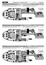
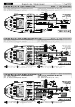
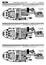
Seguire lo schema di collegamento
CBE25-A005
e
CBE25-A006.
In questo tipo di impianto è consigliabile impostare un ritardo allo spegnimento del
ventilatore su
P21
in modo tale che allo spegnimento della resistenza il ventilatore
continui a girare per smaltirne il calore.
In questo tipo di impianto è possibile avere una regolazione con zona neutra
impostando selezione raffrescamento/riscaldamento automatica (
P02=1
).
Nel caso in cui, in questo tipo di impianto si usi anche la funzione “termostato di
minima”, il ventilatore non sarà mai interdetto quando in modo riscaldamento.
ELECTRIC HEATER SYSTEM
The thermostat can be configured (
P01=2
) to manage a system with an electric
heater for heating the room and a valve that regulates the cool water for cooling the
room.
Follow the wiring diagram
CBE25-A005
and
CBE25-A006.
In this type of system it is suggested to set a delay on the fan switch-off on
P21
, so that
when the electric heater is switched off, the fan keeps running to cool the heater
down.
In this type of system it is possible to have a neutral zone regulation setting the
automatic heating/ cooling selection (
P02=1
).
In case the cut-off temperature function is used in this system, the fan will never be
inhibited while in heating mode.
SISTEMA CON RESISTENZA DI INTEGRAZIONE
Il termostato può essere configurato (
P01=3
) per gestire un impianto speciale avente
due sistemi per riscaldare l’ambiente, uno tramite flusso di acqua calda regolato da
una valvola e l’altro tramite una resistenza elettrica di integrazione.
In questa modalità il termostato pilota solamente una valvola sull’uscita della valvola
freddo e una resistenza di integrazione sull’uscita della valvola caldo.
Schema di collegamento
CBE25-A005
e
CBE25-A006.
INTEGRATING ELECTRIC HEATER SYSTEM
This regulator can be configured (
P01=3
) to manage a special plant type featuring
two heating systems: one with a hot water flow controlled by a valve, the other with
an integrating electric heater. In this mode the regulator is only driving one valve
wired at the cooling output to manage a special plant type featuring two heating
systems: one with a hot water flow controlled by a valve, the other with an integrating
electric heater. In this mode the regulator is only driving one valve wired at the
cooling output and one integrating electric heater wired at the heating output.
The relevant wiring diagram is
CBE25-A005
and
CBE25-A006.
Содержание CBE25
Страница 18: ......


