background image

TC110 Series 
Water Temperature Control Units                 882.03888.00 

• 

09/19/2018


37


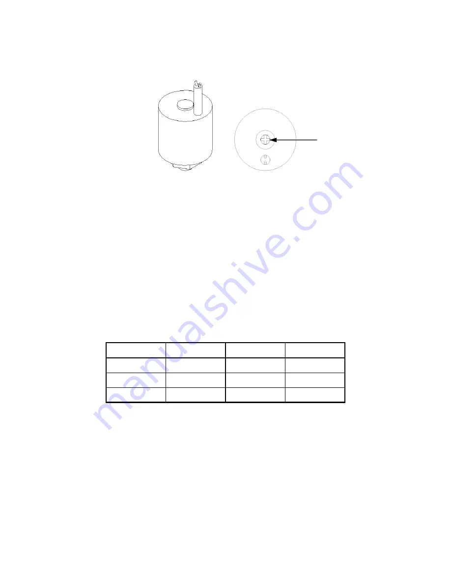
Figure 6:  Pressure Switch - Side View and Top View 


Under the plug is a Phillips-head adjusting screw: 


Turn the screw counterclockwise to reduce the pressure. 

- or - 


Turn the screw clockwise to increase the pressure. 

A quarter turn (90° rotation) approximates 15 psi (103 kPa/ 1.0 bar).


Replace the plug on the top of the switch. 

If the plug gets damaged, the switch is still sealed internally.


Make sure that the high limit on the controller is set to the values listed in the following 
table, based on the switch adjustment. This prevents the pump from cavitating and 
damaging the seal, the switch, and heater element(s). 


psig 

kPa 

Max. temp. °F 

Max. temp. °C 

5 psig 

34 kPa 

227°F 

108°C 

10 psig 

69 kPa 

240°F 

116°C 

15 psig 

103 kPa 

250°F 

121°C 

Safety Thermostat 

Disconnect main power. Open the electrical enclosure and disconnect the neutral lead on 
the safety thermostat from the terminal strip. Protect the stripped lead to prevent short 
circuits. Close the enclosure, reconnect main power, and push the START button and press 
ON/OFF switch to the ON position. The heater should not turn on and the Over 
Temperature
 indicator should illuminate. Disconnect main power before reconnecting the 
thermostat lead
.


Phillips head screw 

Содержание TC110 Series

Страница 1: ...TC110 SERIES WATER TEMPERATURE CONTROL UNITS Part Number 882 03888 00 Revision Date 09 19 2018 OPERATION AND INSTRUCTION MANUAL TC11O...

Страница 2: ...____________ _________________________ _________________________ _________________________ _________________________ _________________________ We are committed to product improvement Specifications ap...

Страница 3: ...Damaged Freight ACS must be notified within 24 hours of any damage The driver should give you a claim number before they leave your facility If the order is collect or third party billing to a custome...

Страница 4: ...ner and packing material to see if you missed any smaller items during unpacking If the Shipment is Not Correct If the shipment is not what you ordered contact the shipping department immediately Plea...

Страница 5: ...ons 16 3 3 External Piping Sizing Considerations 16 3 4 Piping Considerations for Permanent Installations 17 3 5 Piping Considerations for High Mobility Installations 17 3 6 Process Water Consideratio...

Страница 6: ...ocessor Controller 29 4 7 Controller Display 30 4 8 Checking Motor Rotation Direction 31 Maintenance 32 4 9 Preventative Maintenance 33 Every Six Months 33 4 10 Corrective Maintenance 33 Electrical Co...

Страница 7: ...rols in addition to information for operating the machine safely and efficiently The Maintenance chapter is intended to serve as a source of detailed assembly and disassembly instructions for those ar...

Страница 8: ...ty These machines are constructed for maximum operator safety when used under standard operating conditions and when recommended instructions are followed in the maintenance and operation of the machi...

Страница 9: ...nd tools or other metal objects should be left on or around the machine SAFETY GLASSES OR A FACE SHIELD MUST ALWAYS BE WORN when servicing or operating the machine EAR PROTECTION The Occupational Safe...

Страница 10: ...should never be tampered with or removed for ANY reason They should be checked frequently by a qualified mechanic for proper operation NEVER modify the machine configuration or any individual compone...

Страница 11: ...TC110 Series Water Temperature Control Units 882 03888 00 09 19 2018 11 Figure 1 Safety Tags and Warning Labels...

Страница 12: ...o bring the water up to temperature or to changes in the settings when needed The TC110 Series water temperature control unit is a self contained system consisting of a centrifugal pump electric immer...

Страница 13: ...4 Standard Features Compact rugged cabinet with easy access side panels Incoloy immersion heaters with IEC contactors NEMA 1 electrical enclosure Independent high temperature safety thermostat Motor...

Страница 14: ...tative for more information Available options include Heaters upgrade available to 12 kW Manual bypass Auto system water purge mold purge Y strainer Hammer arrestor water hammer shock stop Rubber feet...

Страница 15: ...10 96 1 0 75 35 133 30 207 2 1 50 50 189 30 207 3 2 24 60 227 35 241 5 3 73 75 284 54 372 240 109 7 5 60 90 454 63 434 Figure 2 TC110 Series Unit Full Load Amps Model Full load amps at 460 volts hp kW...

Страница 16: ...Provide a minimum of twelve inches 12 or about 30 cm clearance on all sides of the cabinet to allow circulation of cooling air Locate the unit as close to the process as is practical 3 2 Process Appro...

Страница 17: ...epends on solenoid valve used Common black pipe is recommended for permanent installations TC110 Series water circuit piping is primarily ferrous iron and reacts electro chemically with non ferrous me...

Страница 18: ...and the FROM PROCESS hookup to the exit of the process Connect the COOLING WATER IN to your plant water supply Connect the COOLING WATER OUT line to an open drain or to the return line of your centra...

Страница 19: ...k configured as shown below Check the expansion tank frequently to make sure it is not flooded Water Out Size Depends on Solenoid Valve Used The cooling water outlet leading back to the cooling tower...

Страница 20: ...pressed air inlet marked MOLD PURGE Connect to a clean dry 100 psig 690 kPa 6 9 bar air line Install your own shutoff valve to prevent process liquid from backing up into the plant air piping if the c...

Страница 21: ...flow gpm flow lpm loss psi loss kPa 0 75 hp 0 56 kW 12 7 amps 30 gpm 114 lpm 0 0 psi 0 kPa 1 00 hp 0 75 kW 13 1 amps 35 gpm 133 lpm 1 0 psi 7 kPa 2 00 hp 1 50 kW 14 7 amps 50 gpm 189 lpm 1 5 psi 10 kP...

Страница 22: ...g voltage and amperage requirements and make sure your electrical service conforms before making any electrical connections Total running amps for TC110 Series systems are listed on the nameplate Cust...

Страница 23: ...trical codes 2 The temperature control unit must be grounded in accordance with local standards and codes 3 Voltage must be within plus or minus ten percent 10 of the nameplate rating 4 Make sure your...

Страница 24: ...re that a qualified electrician checks all electrical connections The safety thermostat is preset at the factory to 250 F 121 C It trips at 265 F 129 C The relief valve should be piped to an open unre...

Страница 25: ...OFF rocker switch to the ON to energize the unit and begin the temperature control cycle The switch will be illuminated whenever the unit is on 2 The unit will automatically vent for approximately on...

Страница 26: ...VENT switches and the temperature controller buttons are all that is required to operate this unit After you complete all connections turn the water supply ON then turn control power ON The unit auto...

Страница 27: ...nlikely event of runaway heating If overheating occurs the safety thermostat shuts down heater outputs The unit continues to pump water through the system to prevent heater damage Pressure Relief Valv...

Страница 28: ...ater Hammer Arrestor Shock Stop Optional Shock waves from fast operating solenoid valves may damage some process systems Pump Starter TC110 Series high quality IEC rated pump motor starters are indust...

Страница 29: ...o the pump and heater The vent process is controlled through a timer If you have a large process you may need to complete the venting process by pressing the VENT button on the front mounted switch pa...

Страница 30: ...s thermocouple It also lists parameter symbols during setup and error messages if an error occurs Required Temperature Numeric LED During normal operation the smaller green SP Set Value LED on the con...

Страница 31: ...Arrow key increments or advances the values or settings on the SV Set Value display 4 8 Checking Motor Rotation Direction Check for correct pump rotation direction by looking at the end of the motor...

Страница 32: ...ny remaining pressure in the system Maintenance Never attempt to service a unit until a qualified electrician has opened and locked out the main disconnect using OSHA 1910 147 standards The water supp...

Страница 33: ...ng systems If the unit is allowed to stand idle for a long time before being installed in your factory the housing gasket at the pump can dry out and can possibly leak when the unit is started In most...

Страница 34: ...art After turning off the power supply check the motor shaft to be certain it is free to turn By removing the drip cover on top of the motor you ll have access to the end of the shaft It has been slot...

Страница 35: ...ns must be tight 4 11 Safety Devices Make sure that only qualified electricians test safety devices Safety devices should be tested for function every six 6 months Perform the following procedures for...

Страница 36: ...just the switch to meet your process needs Tools Required Small flat blade screwdriver 2 Phillips head screwdriver HAZARDOUS ELECTRICAL CURRENT PRESENT Maintain a safe ground and disconnect the power...

Страница 37: ...following table based on the switch adjustment This prevents the pump from cavitating and damaging the seal the switch and heater element s psig kPa Max temp F Max temp C 5 psig 34 kPa 227 F 108 C 10...

Страница 38: ...the unit daily for leaks Wipe down the unit periodically to remove dirt and dust buildup especially the motor casing Drain and flush the unit every six 6 months to remove sediment buildup Completely...

Страница 39: ...the machine Be sure that the voltmeter has at least minimum impedance of 5 000 OHMS per volt on AC and 20 000 OHMS per volt on DC scales Popular combination meters VOM and VTVM can be selected to prov...

Страница 40: ...light on Reset and test each leg for balanced amp draws Low pump pressure Pump running in reverse Verify proper rotation If not clockwise reverse any two incoming power leads Foreign matter in the sys...

Страница 41: ...cool Drain is plugged or excessive back pressure is in drain line Clear drain line or eliminate back pressure condition Faulty solenoid valve Test solenoid valve by pressing VENT button and listen fo...

Страница 42: ...ED is on Set process temperature to maximum and check for control voltage at heater contactor Immersion heater elements dirty Remove heater and clean elements Immersion heater element is burned out Ch...

Страница 43: ...r damages for which a purchaser may be liable to other persons damages to property or injuries to any other persons Our sole obligation under this warranty shall be limited to replacing repairing or e...

Страница 44: ...00 09 19 2018 44 Refer to this manual for assistance in installing and maintaining a highly efficient machine Questions regarding areas that are not covered in the manual should be referred to the cu...

Страница 45: ...diting your phone or fax order please have the model and serial number of your unit ready when you contact us TECHNICAL ASSISTANCE If you require any technical assistance we have a qualified service d...

Отзывы: