


ACS Control-System GmbH | www.acs-controlsystem.de | [email protected] | Eggenfelden | Germany
KAK / KLK
page 7 of 16
Installation
Drive the system pressure free prior installation resp. deinstallation of the sensor and avoid high temperatures
to avoid injuries.
Consider enough installation space outside the container or the pipeline to insert the filling level limit switch into
the plant without the use of force.
Install the device if necessary into a bypass if dense heavy foam, wild turbulences or foamed liquids can occur.
Install the filling level limit switch in such a position in the container, where no strong forces to the side, like e.g.
by mixer or near fill-in openings, can have an effect to the electrode rods.
This is especially important for filling level limit switches with especially long electrode rods.
If a metallic wall of a container resp. pipeline should be uses as reference electrode (REF) there must be paid
attention that the metallic process connection of the filling level limit switch is safe electrically conductive
connected with the container resp. the pipeline. Use conductive gaskets like e.g. copper or lead. Isolation
measures like e.g. the wrap of the thread with teflon band or a paper gasket can interrupt the electric contact.
The non-isolated tips of the electrode rods, when mounted, may not make a contact to the wall of the container,
if this is made of metal or electrically conductive plastic.
Electrode rods longer than 0,5 m must be stabilized among each other or against the wall of the container,
especially if the filling liquid is strongly fluctuating.
Use for the stabilization suitable spacers.
The distance between the spaces should be not more than 0,5 m.
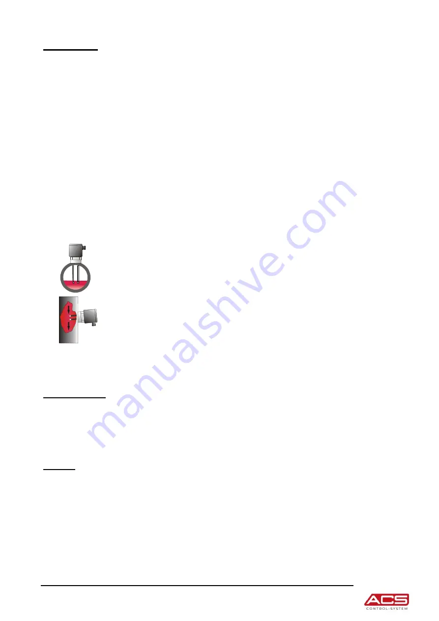
At horizontal pipelines the length of the electrodes is limited by that way, that in a
empty pipe, also in the case of liquid residues, the electrically conductive liquid
connection between electrode and wall resp. between the two electrode rods can
disconnect. Otherwise and empty pipe can be detected as filled.
At horizontal side mounting into a container or also into a pipe for stability reasons the
length of the electrode rods should be not more than 200 mm.
At electrode rods with diameter 8 mm the length can be longer.
At a horizontal mounting the electrode rods should be installed at an angel with the
electrode rod tip below (approx. 20...30°), to allow an easier flow-off of filling material
residues and by this to avoid the coat-forming.
The tightening of the process connection may only be done at the hexagon by a suitable spanner.
The maximum permitted torque strength is 50 Nm.
The screw in of the process connection by using the connection housing is not permitted.
Maintenance
The devices is free of maintenance.
The isolation of the electrodes should be checked regularly and also a possible coating at the electrode rods
should be removed.
A non-conductive coating at the metallic electrode tip can effect error behaviour because no current can flow
although the electrically conductive filling liquid makes a connection.
Repair
A repair may only be carried out by the manufacturer.
If the device must be sent back for repair, the following informations must be enclosed:
An exact description of the application.
The chemical and physical characteristics of the product.
A short description of the occurred error.
Before returning the device for repair, the following measures must be proceeded:
All stick product residues must be removed. This is especially important, if the product is unhealthily,
e.g. caustic, toxic, carcinogenic, radioactive etc.
A returning must be refrained, if it is not possible by 100% to remove the unhealthily product
completely, because e.g. it is penetrate into cracks or is diffused through plastic.
NAMUR


