background image

BusWorks Model XT1533-000


4 CH Current  4 CH Digital I/O w/USB & Profinet 


Acromag, Inc. Tel: 248-295-0880  

            - 38 -                                   

http://www.acromag.com  

- 38 - 

http://www.acromag.com 


SPECIFICATIONS 

Model Number 

 
XT1533-000 (Four Current Output 
Channels combined w/ Four 
Sourcing Digital I/O Channels) 

 
4 AO & 4 DIO Output Channels 
(Combination Current Output 
Module with Sourcing Digital I/O) 
Profinet Support 
DC Powered 
CE Approved 
Includes UL/cUL Class I, Division 2 
approvals 

 
The XT1533-000 is a member of the Acromag DIN-

Rail mounted, “Busworks” family 

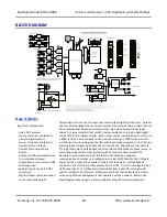
of network I/O modules in the XT Series.  The XT1533-000 model provides four 
channels of DC current output, plus four sourcing digital I/O channels.  This model 
operates over Ethernet using Profinet, but its I/O is setup and calibrated using USB.  

The trailing “

-

000” model 

suffix denotes DC power with CE & UL/cUL Class I, Division 

2 Approvals. 


Models are mounted on standard “T” Type DIN rail and include plug

-in terminals.  

Power can be optionally (or redundantly) bussed along the DIN rail (see Power 
Connections).  Outputs of this model require separate connections to power in order 
to operate them.  Reconfiguration of any XT model will require use of the XT-SIP 
configuration kit, ordered separately (see Accessories section). 


Analog Outputs 

 
Excitation for the analog outputs 
is required at TB3 to operate 
them. 
 

WARNING:

  If you make the 

mistake of connecting 24V 
excitation to the 12V excitation 
terminals, you will damage the 
12V TVS and switching regulator.  
Be very careful when making 
excitation connections to make it 
to the correct terminals.  If 12V 
input is damaged, you can 
connect 24V to the 24V excitation 
terminals to continue operation. 


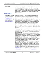
Four separate DC current outputs share return and include transient voltage 
suppression.  You must connect 12V or 24V excitation to operate the outputs 
(connect analog excitation at TB3).  Positive current is pulled from the analog 
excitation supply, sourced from the output channel, and pushed through the load to 
Return (RTN).  The unit must be wired and configured for the intended output (see 
Connections section for details).  The 

following paragraphs summarize this model’s 

analog output type, ranges, and applicable specifications: 


Output Ranges:

  Select 0-20mA DC or 4-20mA DC (a sub-range of 0-20mA range). 

Output Accuracy:

  Factory calibrated to better than ±0.1%.  Manual calibration of 

current outputs can be done to improve output accuracy to better than 0.05%.


Output Load Resistance Range:

  250-550

Ω.  

Maximum output resistance is a 

function of the 14.8V internal voltage rail Vexc, the maximum output current 
Io_max, and the required internal overhead of 2.4V via the relationship R

load_max

 ~ 

(14.8


 2.4)/Io_max.  A minimum load of 22

5Ω is imposed to limit power dissipation 

to safe levels at elevated temperature. 

Analog Output Excitation (TB3):  

There are two separate excitation inputs located at 

TB3: one for 12V power sources (10-15V) and one for 24V power (20-28V).  Both 
excitation sources are diode-coupled to the current output excitation rail, allowing 
analog excitation to be supplied redundantly if required.  See Warning at left. 

Output Overvoltage Protection:

  Bipolar Transient Voltage Suppressers (TVS) with a 

clamp level above 14V typical. 

Output Maximum Current: 

 To simplify programming, the output DAC is normalized 

to 0-30000 for 0-100% of output (or optionally to 0-20000 w/ Legacy support).  This 
16-bit count is digitally limited to 32768 (~109.2%).  This equates to 21.845mA for 
the 0-20mA range, and 21.476mA for the 4-20mA range. 

Output Compliance:

 12.4V typical (with a 14.8V internal excitation rail).  The output 

can thus drive its 21.845mA maximum current into ~567

Ω

 typical.  See the Power 

Requirements 

 Excitation specification. 

Output Update Rate:

  When written & continuously refreshed every 5 seconds. 

Output Cable Length:

  Output interface cables should not exceed 30m in length for 

rated performance. 

Output Temperature Drift:

  Better than 

60ppm/

C (±0.0060%/

C). 


Содержание XT1533-000

Страница 1: ...igital I O 4 DC Current Outputs and 4 Digital Inputs w 4 Tandem High Side Switch Outputs USER S MANUAL ACROMAG INCORPORATED Tel 248 295 0880 30765 South Wixom Road Fax 248 624 9234 Wixom MI 48393 2417...

Страница 2: ...ction 8 Output Connections 10 Digital Input Connections 13 EMI Filter Installation 14 Earth Ground Connections 15 CONFIGURATION SOFTWARE 15 Quick Overview 16 CONFIGURATION STEP BY STEP 18 Getting Conn...

Страница 3: ...ive effects of power wiring component sensor or software failure in the design of any type of control or monitoring system This is very important where property loss or human life is involved It is im...

Страница 4: ...tion offers a convenient daisy chain network connection saving switch ports Operation Diagnostic LED indicators aide trouble shooting Bus Power Ready for Clean Wiring along the DIN Rail and or for Red...

Страница 5: ...e the top groove of the module over the upper lip of the DIN rail Firmly push the unit downward towards the rail until it snaps into place To remove it from the DIN rail first separate the input termi...

Страница 6: ...and can be removed from their sockets by prying outward from the top with a flat head screwdriver blade Strip back wire insulation 0 25 inch on each lead and insert the wire ends into the cage clamp c...

Страница 7: ...RESULT NOTE IT IS RECOMMENDED THAT SUPPLIES CAPABLE OF DELIVERING MORE THAN 2 5A TO THE UNIT BE FUSED WITH A HIGH SURGE TOLERANT FUSE TB6 OF TX6 20 19 18 17 ANY I O TB5 OF TX5 TB4 OF TX4 I O DC POWER...

Страница 8: ...then installed in the field which may be in a hazardous area Do not attempt to connect a PC or laptop to this unit while installed in a hazardous area as USB energy levels could ignite explosive gase...

Страница 9: ...urrent Output 4 CH Digital I O w USB Profinet Acromag Inc Tel 248 295 0880 9 http www acromag com 9 http www acromag com Connect Unit to Power Before USB This unit does not use USB power but requires...

Страница 10: ...e regulator will result Refer to the following figures to wire the current outputs digital outputs and excitation of these models PERSONAL COMPUTER RUNNING WINDOWS OS 1 METER CABLE USB A MALE TO HOST...

Страница 11: ...ent outputs require external analog excitation to operate Outputs do include digital and hardware current limiting There are two analog excitation inputs one for 12V 10 15V another for 24V 20 28V and...

Страница 12: ...he output driver is also powered from the excitation supply IMPORTANT Add Protection with Inductive Loads Outputs do include internal reverse bias shunt diodes to help protect the output switch from d...

Страница 13: ...rn via 10K pull down resistors installed on the board and will never float Observe proper polarity when making I O connections Refer to the following figures to wire the digital inputs of this model I...

Страница 14: ...s outputs and Power order Acromag 4001 135 Laird 28A0592 0A2 or similar for USB cable Acromag 4001 140 and Laird 28A0807592 0A2 or similar for Ethernet cable Acromag 4001 139 Locate ferrites by clampi...

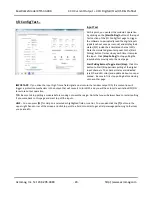
Страница 15: ...of this module CONFIGURATION SOFTWARE While this is an Ethernet network I O module its I O can only be configured and calibrated via its Configuration Software over a USB connection to a Windows based...

Страница 16: ...up Device Select First Connect to the Unit Here Select from connected modules and Open or Close communication with them Display the Model Serial Number and Manufacturer of the connected module and rep...

Страница 17: ...ic for the tandem digital input channel useful for i2o operation Choose Legacy Support Yes if you want the output to scale 0 100 to 0 20000 versus 0 100 to 0 30000 Optional invert Input Logic of input...

Страница 18: ...ired 4 Connect Power You need to connect power from 12 32V to power this module Current required will vary with voltage level refer to Specifications Your supply must be capable of providing at least...

Страница 19: ...USB hub you can use the Device scroll field to select another unit using the serial information suffix of the Device Model number to discern one unit from another Once you have selected a device click...

Страница 20: ...efines one host from all other computers hosts on the Internet The IP address is made up of four octets 8 bits each octet having a value between 0 255 00H FFH It is expressed here in decimal form with...

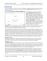
Страница 21: ...fault the module is setup to use Static IP Addressing and a default Static IP Address of 192 168 1 100 You can optionally choose to have the IP address assigned dynamically via DHCP but this will addi...

Страница 22: ...tively then click Send Config to write the channel configuration to the unit or more simply make changes to many channels and then click Send Config one time to write all the channel configurations to...

Страница 23: ...gital outputs Analog Output Test There are 8 or 4 analog output fields that allow you to enter or read output values in volts XT154x or mA XT153x Read Analog Output Click this button to read the curre...

Страница 24: ...this button to Start Stop periodic polling of the digital input channels The channel states are indicated via 1 0 and LED color and updated about once per second Be sure to first stop polling before...

Страница 25: ...conds of slide or arrow inactivity Simply set the output to precisely 1mA using a meter to measure the output a live zero is used instead of 0mA to improve the accuracy of calibration click the zero b...

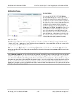
Страница 26: ...messages like No Error Transfer Error and Timeout Error after clicking OK during calibration If you encounter a Transfer or Timeout Error you may have to repeat the calibration process HELP You can pr...

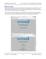
Страница 27: ...t this address on the Device Communication Setup page of the USB Configuration Software for the unit the default is 192 168 1 100 This will access the home page of the unit similar to the first screen...

Страница 28: ...f a 32 bit microcontroller Each output source is pulled down to return via a 10K resistor and is fed back to the controller through a 100K series resistor which drives non inverting input buffers with...

Страница 29: ...plication layer protocol TCP IP especially selected for industrial automation applications In this way Profinet offers scalable performance with protocols providing three different data channels TCP I...

Страница 30: ...etwork a Profinet IO Controller must be programmed with a special Profinet Configuration tool such as Step7 from Siemens Profinet IO devices like this module are also configured using a Profinet confi...

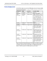
Страница 31: ...me reason OUTPUT Consumed DO Channel 3 2 1 0 Unsigned 16 bit Bits 3 0 Bits 15 4 Not Used OUTPUT Consumed AO Channel 0 Unsigned 16 bit Normalized count from 0 30000 or 0 20000 w Legacy support represen...

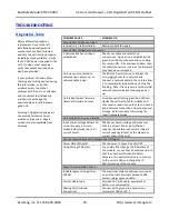
Страница 32: ...is bad The RUN LED will continue to blink as the unit initially hunts for a network link Connect a network cable to the unit to allow it to complete its initialization and stop the blinking Note this...

Страница 33: ...hen select and re open the module for communication or simply exit the Configuration software and reboot it Cannot Communicate with Module via USB A missing USB Isolator could cause a ground loop betw...

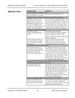
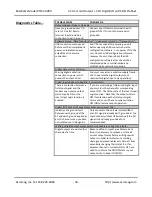
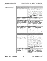
Страница 34: ...ppear to Register Incorrect State There is contention between a field input signal and the tandem open source output which may be ON or the Invert Input Logic function is enabled If you are monitoring...

Страница 35: ...ally by connecting 24V to it by mistake Connecting 24V power to the 12V analog excitation terminals will destroy its TVS and switching regulator In this case connect 24V excitation 20 28V to the 24V t...

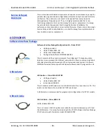
Страница 36: ...rface Package Configuration Kit Order XT SIP USB Signal Isolator USB A B Cable 4001 112 USB A mini B Cable 4001 113 Configuration Software CDROM 5041 094 This kit contains all the essential elements f...

Страница 37: ...onnections to Power Two end stops 1027 222 used to secure the terminal block and module for hazardous location installations Low EMI Double Shielded Patch Cable Ethernet Patch Cable 3 feet long Model...

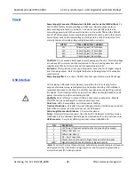
Страница 38: ...sitive current is pulled from the analog excitation supply sourced from the output channel and pushed through the load to Return RTN The unit must be wired and configured for the intended output see C...

Страница 39: ...count or the normalized count For normalization to 30000 the effective resolution is dominated by the 16 bit raw DAC resolution at 1 part in 29533 But for normalization to 20000 the effective resolut...

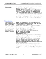
Страница 40: ...wn to help protect the output channel from damage due to overload cycle excitation OFF ON to restore output operation after a shutdown Output Thermal Shutdown Individual outputs will shutdown and latc...

Страница 41: ...gnal it shuts OFF and you must cycle output excitation OFF ON to restore output operation Digital Inputs This model has four tandem digital input and output channels No additional excitation is requir...

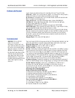
Страница 42: ...001 of output span effect per volt DC change USB Interface Unit includes a USB socket for temporary connection to a PC or laptop for the purpose of channel setup reconfiguration and trouble shooting U...

Страница 43: ...e metal shield circuit of the network connectors is isolated and capacitively coupled to the input power minus terminal via an isolation capacitor Network to Network Isolation Network ports are additi...

Страница 44: ...double shielded Ethernet cable is also helpful in curbing emissions These limits represent the minimum requirements of the applicable standard but this product has typically been tested to comply with...

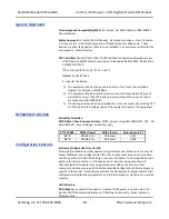
Страница 45: ...ed that is set at a level not exceeding 140 of the peak rated voltage value at the supply terminals to the equipment Reliability Prediction Reliability Prediction MTBF Mean Time Between Failure MTBF i...

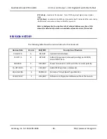
Страница 46: ...l Reference section of this manual for detailed information on available software control of this model REVISION HISTORY The following table shows the revision history for this document Release Date V...

Отзывы: