BusWorks Model XT1533-000
4 CH Current 4 CH Digital I/O w/USB & Profinet
Acromag, Inc. Tel: 248-295-0880
- 17 -
http://www.acromag.com
- 17 -
http://www.acromag.com
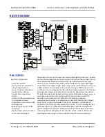
Quick Overview
…
HELP
–
Press F1 for Help on a selected or highlighted field or
control. You can also click the [?] button in the upper-right hand
corner of the screen and then click to point to a field or control to
get a Help message pertaining to the item you pointed to.
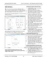
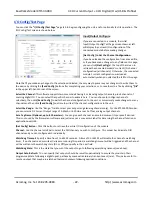
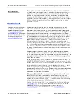
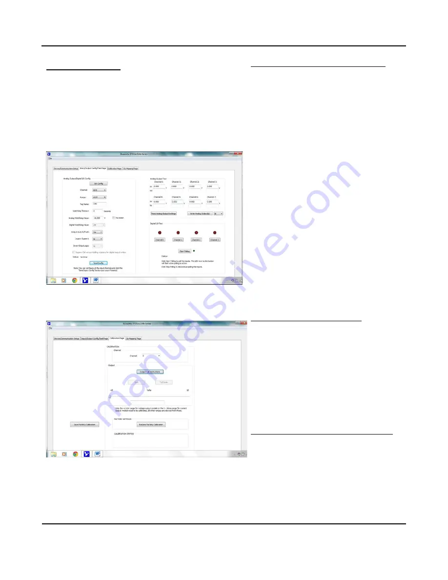
If you click on the I/O Config/Test Page tab, a screen similar to the
following will appear:
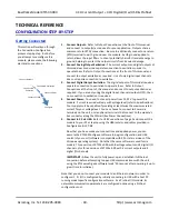
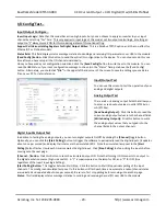
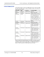
After configuring and/or testing your channels, you can click on
the Output Calibration tab to display the following screen:
For a more detailed configuration procedure, see the
Configuration Step-by-Step section of the Technical Reference
on page 18 of this manual.
I/O Configure (Configure I/O Channels Here)
•
Use
[Get Config]
to retrieve the connected
module’
s I/O configuration.
•
Select the specific channel to configure.
•
Set the range for the analog output channel.
•
Optionally apply a Tag Name to the channel for
reference over USB (up to 8 characters).
•
Configure a watchdog timer for the output
channel and a Timeout value or state. Setup
auto-refresh for the outputs to combat digital
upset or force a restart following thermal
shutdown (digital outputs). You can even
choose to invert the logic for the tandem digital
input channel, useful for i2o operation.
•
Choose Legacy Support=”Yes” if yo
u want the
output to scale 0-100% to 0-20000, versus 0-
100% to 0-30000.
•
(Optional) invert Input Logic of input channels.
•
Support Coil versus Holding Registers: This is a
Modbus TCP/IP option and has no effect for
Ethernet/IP and Profinet models.
•
Read the status of your configuration message
over USB in the Status field.
•
Use
[Send Config]
to send your configuration to
the connected unit and read message Status.
C
lick [Send…] one time after setting up each
channel and all channels will be written at once.
Analog Output & Digital Output Test
After making I/O configuration changes, you can use
the I/O Test controls to verify operation of your I/O.
•
Read the current analog output settings by
clicking [Read Analog Output Settings].
•
Click [Write Analog Outputs] to set the output
level to the values entered into channel fields.
•
Turn digital outputs On/Off
with [Channel…]
.
•
Use [Start/Stop Polling] to poll digital inputs.
•
Display the current state of the inputs with
simulated LED’s and “1” or “0” superimposed on
the lamps for ON or OFF.
Calibration Page (Calibrate Your Outputs Here)
If you have excessive error, use the controls of this
page to calibrate each Output channel separately.
•
Click the
[Output Cal Instructions]
button to
begin output calibration and follow the prompts
to calibrate output Zero and Full-scale.
•
Use
[Zero]
and
[Full Scale]
and measure the
output range zero or full-scale signal and enter
the measured value here.

