


SERIES IP445 INDUSTRIAL I/O PACK 32 CHANNEL ISOLATED SSR OUTPUT MODULE
___________________________________________________________________________________________
- 4 -
CARD CAGE CONSIDERATIONS
Refer to the specifications for loading and power requirements.
Be sure that the system power supplies are able to accommodate
the power requirements of the carrier board, plus the installed IP
modules, within the voltage tolerances specified.
IMPORTANT: Adequate air circulation must be provided to prevent
a temperature rise above the maximum operating temperature.
The dense packing of the IP modules to the carrier board
restricts air flow within the card cage and is cause for concern.
Adequate air circulation must be provided to prevent a temperature
rise above the maximum operating temperature and to prolong the
life of the electronics. If the installation is in an industrial
environment and the board is exposed to environmental air, careful
consideration should be given to air-filtering.
BOARD CONFIGURATION
Power should be removed from the board when installing IP
modules, cables, termination panels, and field wiring. Refer to
Mechanical Assembly Drawing 4501-434 and your IP module
documentation for configuration and assembly instructions. Module
IP445 digital output boards have no hardware jumpers or switches to
configure. Software configurable control registers are provided for
control of all modes of operation. Refer to section 3 for
programming details.
This module is built with socketed output pull-up resistors
installed. These may be used when the SSR’s are applied as low
side switches. Resistor values may be changed if needed, and the
resistors may be removed for high side switching (see IP445
Resistor Location Drawing 4501-606).
CONNECTORS
IP Field I/O Connector (P2)
P2 provides the field I/O interface connections for mating IP
modules to the carrier board. P2 is a 50-pin female receptacle
header (AMP 173279-3 or equivalent) which mates to the male
connector of the carrier board (AMP 173280-3 or equivalent). This
provides excellent connection integrity and utilizes gold-plating in the
mating area. Threaded metric M2 screws and spacers are supplied
with the module to provide additional stability for harsh environments
(see Mechanical Assembly Drawing 4501-434). The field and logic
side connectors are keyed to avoid incorrect assembly.
P2 pin assignments are unique to each IP model (see Table 2.1)
and normally correspond to the pin numbers of the field I/O interface
connector on the carrier board (you should verify this for your carrier
board).
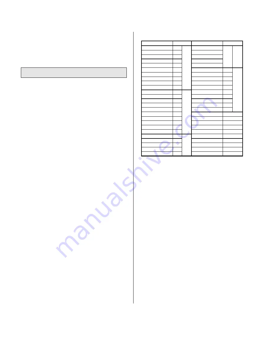
Table 2.1: IP445 Field I/O Pin Connections (P2)
Pin Description
Number
Pin Description
Number
OD00
1
OD20
26
P
OD01
2
OD21
27
O
OD02
3
P
OD22
28
R
OD03
4
O
OD23
29
T
User Supply 0
5
R
User Com Out 2
30
2
OD04
6
T
OD24
31
OD05
7
OD25
32
OD06
8
0
OD26
33
P
OD07
9
OD27
34
O
User Com Out 0
10
User Supply 3
35
R
OD08
11
OD28
36
T
OD09
12
OD29
37
OD10
13
P
OD30
38
3
OD11
14
O
OD31
39
User Supply 1
15
R
User Com Out 3
40
OD12
16
T
Not Used
41
OD13
17
Not Used
42
OD14
18
1
Not Used
43
OD15
19
Not Used
44
User Com Out 1
20
Not Used
45
OD16
21
P
Not Used
46
OD17
22
O
Not Used
47
OD18
23
R
Not Used
48
OD19
24
T
Not Used
49
User Supply 2
25
2
Not Used
50
The output channels of this module are divided into four ports of
eight channels each. All channels within a port share a common
signal connection with each other. Isolation is provided between the
ports and the IP logic. In addition, bus isolation is provided between
ports.
P2 pin assignments are arranged to be compatible with similar
Acromag models. This model is directly loopback compatible with
the Acromag Model IP440 32-Channel Digital Input Board.
Likewise, pin assignments are identical to those of Acromag Model
IP405 40-Channel Digital Output Boards for channels 0-31, except
for the user supply connections. This model (remove socketed pull-
up resistors) may also interface with industry accepted I/O panels,
termination panels, and relay racks when used with the Acromag
Model 5025-655 I/O Adapter Card. However, relay racks are usually
isolated in which case it would probably be more efficient to use the
non-isolated IP405 module. Consult the factory for information on
these and other compatible products.
Refer to Drawing 4051-604 for example field output
connections. See Drawing 4501-603 for loopback connections to
Acromag Model IP440 Input Modules.
Note that the outputs of this module are bipolar, and may be
connected in any direction with respect to the port common.
Further, do not confuse port commons with signal ground. For the
IP445, port common only infers that this lead is connected common
to the 8 outputs of the port (a separate common for each port). The
port commons of the IP445 output module and IP440 input
module are normally not connected together for loopback
interconnection (see Drawing 4501-603).
Artisan Technology Group - Quality Instrumentation ... Guaranteed | (888) 88-SOURCE | www.artisantg.com
Содержание IP445 Series
Страница 12: ...Artisan Technology Group Quality Instrumentation Guaranteed 888 88 SOURCE www artisantg com...
Страница 13: ...Artisan Technology Group Quality Instrumentation Guaranteed 888 88 SOURCE www artisantg com...
Страница 14: ...Artisan Technology Group Quality Instrumentation Guaranteed 888 88 SOURCE www artisantg com...
Страница 15: ...Artisan Technology Group Quality Instrumentation Guaranteed 888 88 SOURCE www artisantg com...
Страница 16: ...Artisan Technology Group Quality Instrumentation Guaranteed 888 88 SOURCE www artisantg com...
Страница 17: ...Artisan Technology Group Quality Instrumentation Guaranteed 888 88 SOURCE www artisantg com...
Страница 18: ...Artisan Technology Group Quality Instrumentation Guaranteed 888 88 SOURCE www artisantg com...
Страница 19: ...Artisan Technology Group Quality Instrumentation Guaranteed 888 88 SOURCE www artisantg com...
Страница 20: ...Artisan Technology Group Quality Instrumentation Guaranteed 888 88 SOURCE www artisantg com...


