SERIES AP470 ACROPACK
USER
’S MANUAL
Acromag, Inc. Tel: 248-295-0310
- 29 -
http://www.acromag.com
- 29 -
www.acromag.com
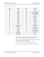
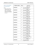
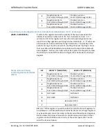
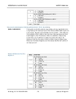
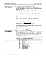
5
Negative Events on
Port 2 I/O20 through I/O23
Positive Events on
Port 2 I/O20 through I/O23
6
Negative Events on
Port 3 I/O24 through I/O27
Positive Events on
Port 3 I/O24 through I/O27
7
Negative Events on
Port 3 I/O28 through I/O31
Positive Events on
Port 3 I/O28 through I/O31
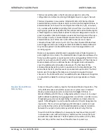
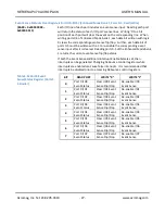
Event Polarity Control Register For Ports 4 & 5 (Enhanced Mode Bank 1, Port 7, Write Only)
(BAR0 + 0x0000 0024)
A write to this register controls the polarity of the input sense event for
nibbles of ports 4 & 5 (channels 32-47, four channels at a time). A “1”
written to a bit in this register will cause the corresponding event sense
input lines to flag negative events (high-to-low transitions). A “0” will cause
positive events to be sensed (low-to-high transitions). The polarity of the
event sense logic must be set prior to enabling the event input logic. Note
that no events will be detected until enabled via the Event Sense Status &
Clear Register. Further, interrupts will not be reported to the system unless
the Interrupt enable bit-0 has been configured for enable via the Interrupt
Register.
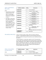
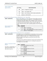
Table 3.14 Event Polarity
Control Register For Ports 4&5
(Port 7)
BIT
WRITE “1” (NEGATIVE)
WRITE “0” (POSITIVE)
0
Negative Events on
Port 0 I/O32 through I/O35
Positive Events on
Port 0 I/O32 through I/O35
1
Negative Events on
Port 0 I/O36 through I/O39
Positive Events on
Port 0 I/O36 through I/O39
2
Negative Events on
Port 1 I/O40 through I/O43
Positive Events on
Port 1 I/O40 through I/O43
3
Negative Events on
Port 1 I/O44 through I/O47
Positive Events on
Port 1 I/O44 through I/O47
4
NOT USED
NOT USED
5
NOT USED
NOT USED
6
Bank Select Bit 0
7
Bank Select Bit 1
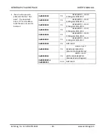
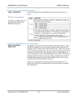
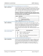
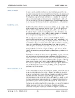
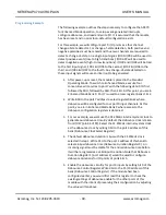
Bits 6 & 7 of this register are used to select/monitor the bank of registers to
be addressed. In Enhanced Mode, three banks (banks 0-2) of eight registers
may be addressed. Bank 0 is similar to the Standard Mode bank of registers.
Bank 1 allows the 48 event inputs to be monitored and controlled. Bank 2
registers control the debounce circuitry of the event inputs. Bits 7 and 6
select the bank as follows:

