background image

BusWorks® 961/962EN User’s Manual              Modbus TCP/IP Differential I/V Input 
___________________________________________________________________ 


_______________________________________________________________________________________
Acromag, Inc.   Tel:248-624-1541  Fax:248-624-9234   Email:

[email protected]

  http://www.acromag.com 

17

 
Upon power-up, the green “Run” LED should light.  A continuous blinking 
Run LED indicates “wink” ID mode.  If the Run LED remains OFF and 
correct power has been applied, then either the internal power supply has 
failed or a fatal processor error (firmware) has occurred. 
 

SYMPTOM 

POSSIBLE CAUSE 

POSSIBLE FIX 

Green RUN LED 
does not light. 

In3.3V power 
has failed. 

Return module for repair. 

Continuous flashing 
green RUN LED. 

Module in “wink” 
mode. 

Read Module Status register 
to verify “wink” status.  Write 
5555H to Wink Mode 
Toggle Register to toggle 
wink mode off/on. 

Cannot 
communicate. 

Power ON at the 
module? 

Check power.  Is green 
RUN LED ON? 


Connecting cable is 
not a crossover 
cable. 


TIP:

  To check cable 

type, hold both ends 
in same position and 
read the wire colors 
through the clear 
portion of the plug 
from left to right.  If 
colors are arranged in 
the same order, you 
have a straight cable. 


This module’s ethernet port 
is wired MDI.  You must use 
a crossover cable when 
connecting this module to 
your PC or another device 
also wired MDI.  If you are 
connecting to an Ethernet 
switch or hub, then a direct 
cable is used. 

Note:

  If your Link LED is 

ON, you have connected 
using the correct type of 
cable, but it could still be 
defective. 


Wrong IP Address 

Change the IP address of 
the module or the PC so 
that both match.  Try the 
default module address of 
128.1.1.100.  For the PC 
NIC, try another address. 

Many 
Communication 
Errors. 

Is cable segment 
longer than 100M? 

Maximum distance between 
two nodes is limited to 100 
meters using approved 
cable. 


Correct Cable? 

Shielded CAT-5/5E cable or 
equivalent is recommended. 


Missing earth ground 
connection. 

Connect earth ground to 
TB3-33 GND terminal 
adjacent to power terminal. 

Cannot Browse 
Module. 

Your browser may be 
setup to use a proxy 
server for LAN 
communications. 

Temporarily disable the use 
of a proxy server by your 
browser (see procedure of 
next page). 


TROUBLE-
SHOOTING 

Diagnostics Table 

If your problem still exists after 
checking your wiring and 
reviewing this information, or if 
other evidence points to 
another problem with the unit, 
an effective and convenient 
fault diagnosis method is to 
exchange the module with a 
known good unit.  Acromag’s 
Application Engineers can 
provide further technical 
assistance if required.  
Complete repair services are 
also available from Acromag. 

Содержание 961EN-4006

Страница 1: ...ent Inputs Model 962EN 4006 Six Differential Voltage Inputs USER S MANUAL ACROMAG INCORPORATED Tel 248 624 1541 30765 South Wixom Road Fax 248 624 9234 P O BOX 437 Wixom MI 48393 7037 U S A Copyright...

Страница 2: ...18 Getting Out Of Trouble 18 TECHNICAL REFERENCE KEY FEATURES 19 HOW IT WORKS 20 ABOUT MODBUS TCP IP 21 IP Addressing 21 Dynamic Host Configuration Protocol 23 Domain Name System DNS 23 MODBUS REGIST...

Страница 3: ...006 IN4 44 41 36 33 PWR NETWORK 13 IN0 16 IN1 21 24 IN2 TB3 TB1 GND INPUTS 4 5 IN5 46 43 45 RX 35 42 DC DC 32 31 34 TB1 11 14 12 IN0 TB2 22 15 TX IN1 5V 3V TB4 TB4 25 23 26 IN3 IN2 IN3 INPUTS 2 3 DC P...

Страница 4: ...il until it snaps into place To remove first separate the input terminal block s from the bottom side of the module to create a clearance to the DIN mounting area Next while holding the module in plac...

Страница 5: ...ED MDI ETHERNET SWITCHES AND HUBS ARE WIRED MDI X THE ACROMAG ETHERNET SWITCH IS AUTOMATIC MDI MDI X AND ELIMINATES THE NEED FOR MAKING A DISTINCTION BETWEEN THE USE OF STRAIGHT THROUGH MDI AND CROSSO...

Страница 6: ...WIRE TRANSMITTER 961EN 5020 350 SENSOR AC CURRENT SENSOR INPUT 961EN 9 Connect 15 36V DC to the power terminals labeled DC DC Observe proper polarity For supply connections use No 14 AWG wires rated f...

Страница 7: ...R S IN1 IN1 FIELD XMTR 250 OHMS IN0 IN0 INP DCS PLC TB1 DIFFERENTIAL VOLTAGE MONITORING Temperature Pressure Level Flow Speed CHART RECORDER DATA LOGGER OR TRANSMITTER 962EN 24V DC 250 OHMS OUT NOTE 9...

Страница 8: ...web pages of this module that are used to configure the network parameters change the user name and password map inputs to calibrate the module and operate test the module For each new browser session...

Страница 9: ...s you may be prompted to re enter your new username and password before being permitted to move to other pages You can click the Network Configuration Page button to set the network configuration para...

Страница 10: ...ddresses while the DHCP server is responsible for dynamically passing out IP addresses A Subnet Mask is used to subdivide the host portion of the IP address into two or more subnets The subnet mask wi...

Страница 11: ...ocol refers to a protocol for assigning dynamic IP addresses to devices on a network With dynamic addressing a device can have a different IP address every time it connects to the network In some syst...

Страница 12: ...pdate time Note that the target output channels may still be controlled independently but their level will be overwritten by subsequent mapped messages when enabled Use the scroll bar on the right to...

Страница 13: ...e on the network Map To Holding Register Address Specify a valid 4xxxx holding register address in the target device for writing to the output For the 972 973EN only addresses 40019 to 40024 will appl...

Страница 14: ...ration Control of this page to change the input range for each channel group 0 1 2 or 3 4 5 For the 961EN shown you may select from 0 20mA 4 20mA 0 11 17mA and 0 1mA DC current ranges For the 962EN yo...

Страница 15: ...t register access as described in Method 2 of the following page Your success in recalibrating the input will strongly depend upon the accuracy and precision of your signal source If recalibration of...

Страница 16: ...continue Repeat this process for the other endpoint span 7 Repeat steps 2 5 for the other input channels to be calibrated Method 2 Calibration Via The Modbus TCP IP Interface 1 Write to the appropria...

Страница 17: ...s ethernet port is wired MDI You must use a crossover cable when connecting this module to your PC or another device also wired MDI If you are connecting to an Ethernet switch or hub then a direct ca...

Страница 18: ...revent you from writing invalid values to a configuration register As such if you inadvertently write an invalid value to an internal register you could cause the module to become inoperable under cer...

Страница 19: ...D EFT and other transients 10Base T and 100Base TX Support Integrated IEEE 802 3 802 3u 100Base TX 10Base T Auto Negotiated 10 100Mbps Half or Full Duplex Flexible Multi Range Analog Inputs Accepts ei...

Страница 20: ...le The current input model 961EN uses precision 24 9 current sink resistors across the inputs Voltage input models use 10 1 precision resistor voltage dividers at the input A multiplexer is used to co...

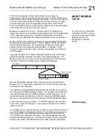
Страница 21: ...ng data Modbus A Modbus TCP IP message is simply a Modbus communication encapsulated in an Ethernet TCP IP wrapper In practice Modbus TCP embeds a Modbus data frame into a TCP frame without the Modbus...

Страница 22: ...k of 255 255 255 0 then the first three numbers represent this Class C network at address 128 1 1 0 the last number identifies a unique host node on this network node 100 at address 128 1 1 100 A Subn...

Страница 23: ...xxx Read Input Registers A 3x reference register contains a 16 bit number received from an external source e g an analog signal 4xxxx Read Write Output or Holding Registers A 4x register is used to st...

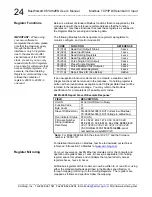
Страница 24: ...1 FIELD DESCRIPTION Unit ID Echo Unit ID Sent In Query Function Code 11 Byte Count 42 Slave ID Model No 00 961EN 4006 6 Diff Current In w Modbus 01 962EN 4006 6 Diff Voltage In w Modbus Run Indicator...

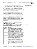
Страница 25: ...il ON Writing to multiple coils is not supported via register mirroring you must use the Write Multiple Coils function for that Note that with respect to Acromag 9xxMB Modbus RTU modules only 3xxxx In...

Страница 26: ...atus Bit 15 0 Not Used Bit 14 Wink Mode Flag 1 Wink Mode Blinks Run LED for ID 0 Normal Operation See Wink Module Register Bit 13 Default Mode Flag 1 Default Mode Indicator 0 Not Default Mode Bits 12...

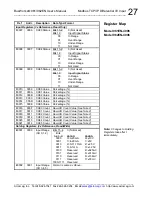
Страница 27: ...0009 CH00 Value Percentage 30011 000A CH01 Value Percentage 30012 000B CH02 Value Percentage 30013 000C CH03 Value Percentage 30014 000D CH04 Value Percentage 30015 000E CH05 Value Percentage 30016 00...

Страница 28: ...0F Reserved Do Not Use 40017 0010 Reserved Do Not Use 40018 0011 Reserved Do Not Use 40019 0012 Reserved Do Not Use 40020 0013 Reserved Do Not Use 40021 0014 Calibration Access And Wink Mode Toggle An...

Страница 29: ...40031 001E CH0 Cal Lo Range 4 Raw A D Count Value See Note 2 625mV 962EN 40032 001F CH0 Cal Hi Range 5 Raw A D Count Value See Note 2 313mV 962EN 40033 0020 CH0 Cal Lo Range 5 Raw A D Count Value See...

Страница 30: ...ue See Note 2 4 20mA 961EN or 5V 962EN 40057 0038 CH2 Cal Lo Range 1 Raw A D Count Value See Note 2 4 20mA 961EN or 5V 962EN 40058 0039 CH2 Cal Hi Range 2 Raw A D Count Value See Note 2 0 11 17mA 961E...

Страница 31: ...See Note 2 313mV 962EN 40081 0050 CH3 Cal Lo Range 5 Raw A D Count Value See Note 2 313mV 962EN 40082 0051 CH3 Cal Hi Range 6 Raw A D Count Value See Note 2 156mV 962EN 40083 0052 CH3 Cal Lo Range 6 R...

Страница 32: ...unt Value See Note 2 4 20mA 961EN or 5V 962EN 40106 0069 CH5 Cal Hi Range 2 Raw A D Count Value See Note 2 0 11 17mA 961EN or 2 5V 962EN 40107 006A CH5 Cal Lo Range 2 Raw A D Count Value See Note 2 0...

Страница 33: ...0081 Ideal Range 6 Hi Ideal A D Count Value See Note 2 156mV 962EN 40131 0082 Ideal Range 6 Lo Ideal A D Count Value See Note 2 156mV 962EN 40132 0083 Ideal Range 7 Hi Ideal A D Count Value See Note 2...

Страница 34: ...a group network and power are isolated from each other Non volatile reprogrammable memory in the module stores configuration and calibration information The BusWorks model prefix 900 denotes the Serie...

Страница 35: ...to the 961EN s process current input terminals Input Burden A function of the wire gauge resistance used for primary turns the current carrying wire being monitored AC Current Sensor to Transmitter Wi...

Страница 36: ...ide 4 68 inches tall 4 35 inches deep Refer to the dimensions drawing at the front of this manual DIN Rail Mount Type EN50022 T rail 35mm I O Connectors Removable plug in type terminal blocks rated fo...

Страница 37: ...n Degree 2 environment with an installation category over voltage category II rating Electromagnetic Interference Immunity EMI Unit has demonstrated measurement shift less than 0 25 of input span with...

Страница 38: ...s or 100Mbps Duplex Auto negotiated Full or Half Duplex Compliance IEEE 802 3 802 3u 802 3x Modbus TCP IP Protocol Support Up to 10 sockets may be selected Web pages for configuration and control are...

Страница 39: ...esigned for use in harsh industrial environments Acromag recommends the use of shielded cable when wiring to this device Select STP Shielded Twisted Pair cable rather than UTP Unshielded Twisted Pair...

Страница 40: ...e and an RJ45 plug at both ends This cable performs the Ethernet crossover function and is used to connect a PC directly to an Acromag Series 9xxEN I O module Note that you do not need to use a crosso...

Отзывы: