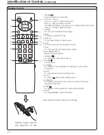
Identification of Controls
(continued)
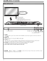
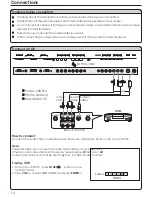
Main unit (rear view)
1. RS232 terminals
2. DVI input /Audio in
3. VGA input /Audio in
4. Component inputs 1
5.
8. AV inputs
Receives the digital video/audio signals from a set top box.
Connect to the audio and component output jacks of a DVD player or Set-Top Box.
Connect to the audio and component output jacks of a DVD player or Set-Top Box.
(
Connect to the VCR input jacks to record programs.
Receive video/audio signals from external sources such as VCR or DVD player.
Allows you to connect cable or outdoor antenna.
Receive a S-Video signal from external source such as VCR or DVD player. (Note: S-Video
Shares audio input with AV input.
Connect to the VGA/audio output jacks on your PC.
(Y, Pb/Cb, Pr/Cr, Audio)
Video, Audio L, R)
(Video, Audio L, R)
Component inputs 2
(Y, Pb/Cb, Pr/Cr, Audio)
6. Headphone jack
7. AV outputs
9. Antenna input
10. S-Video input
For service use only. The user cannot operate the unit through the RS232 terminals.
SVHS
HEADPHONE
RF
PIC
AUDIO
PIC
AUDIO
DVI
AV OUTPUT
AV INPUT
CONTROL
COMPONENT INPUT 1
COMPONENT INPUT 2
D-SUB
AUDIO
AUDIO
C /P
r
r
C /P
r
r
C /P
b
b
C /P
b
b
Y
Y
VIDEO
VIDEO
R
L
AUDIO
R
L
AUDIO
R
L
SPEAKER
R
L
SPEAKER
Speaker output jacks
AC- INPUT
AC- INPUT
D-SUB
SVHS
HEADPHONE
RF
PIC
AUDIO
PIC
AUDIO
DVI
AV OUTPUT
AV INPUT
CONTROL
COMPONENT INPUT 1
COMPONENT INPUT 2
D-SUB
AUDIO
AUDIO
C /P
r
r
C /P
r
r
C /P
b
b
C /P
b
b
Y
Y
VIDEO
VIDEO
R
L
AUDIO
R
L
AUDIO
BOTTOM VIEW
AC power
input socket
1
2
3
4
5
6
7
8
9
10
9


