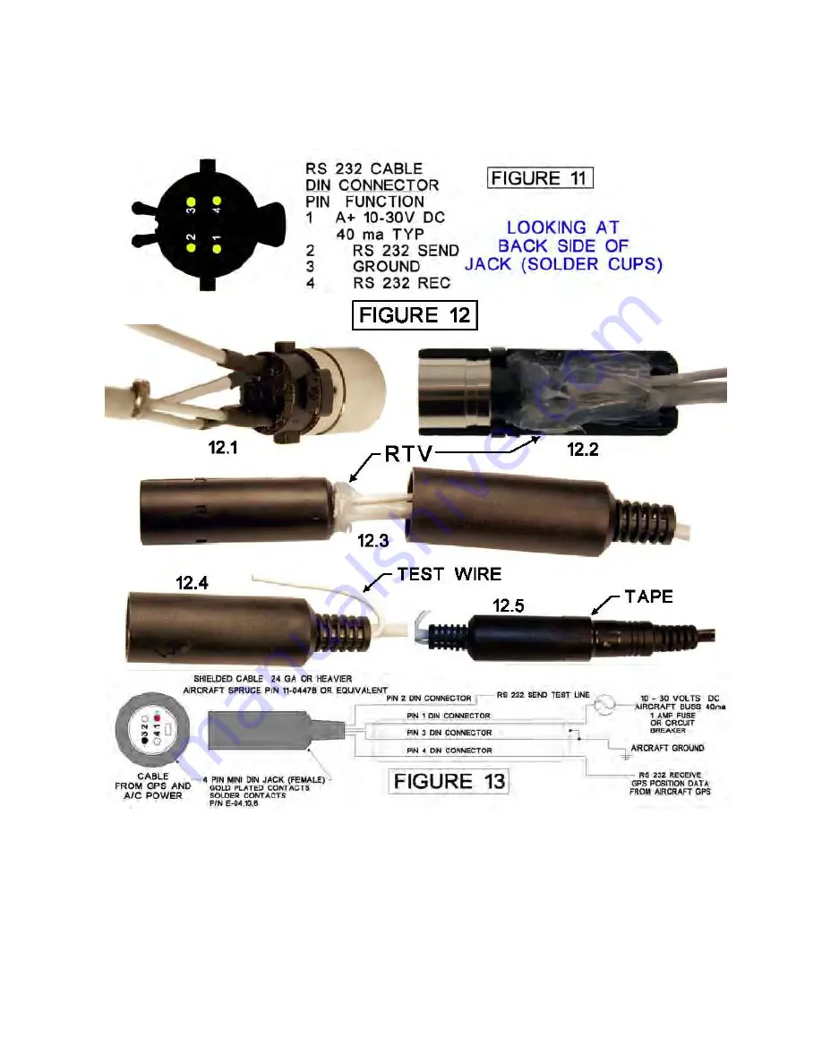
6.) Solder the connections, seal the back of the jack, and wire solder joints with silicon
RTV sealant. (Loctite 59530 or equivalent) (Fig. 12.2)
7.) Apply RTV sealant to the inside of the outer cover to seal the wire where it enters the
outer housing. (Fig. 12.3)
8
SECTION 7 FINAL INSTALLATION AND CHECK OUT
1.) After installing the ELT, antenna, and RCPI in the aircraft, install the coaxial cable
between the ELT transmitter, and antenna base. If possible the cable should not cross any
production breaks in the airframe, and must have a reasonable amount of slack at the
transmitter. The slack is necessary for easy removal of the coaxial cable during
maintenance. If a longer cable than the one supplied with the unit (5 foot) is needed, it may
be fabricated using RG-58 cable or equivalent, and Amp 227079-5 connectors or their
equivalent. Insertion loss of the cable at the 121.5 MHz frequency should not exceed 3dBm,
and at the 406 MHz frequency 2dbm. Secure the coaxial cable using tie wraps or other
appropriate methods. Make sure the cable is protected from abrasion.
Содержание E-04
Страница 16: ...16 SECTION 16 MAJOR PARTS ...
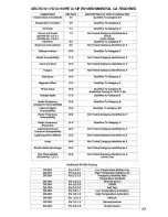
Страница 17: ...17 SECTION 17 DO 160F ED 14F ENVIRONMENTAL CATEGORIES ...


