SECTION 4 REMOTE CONTROL INSTALLATION
IMPORTANT YOU MUST INSTALL A BATTERY IN THE REMOTE.
The remote control panel indicator (RCPI) P/N E-04.5 is designed to be powered by a single
Duracell PX28L 6 volt Lithium battery, or equivalent. Alkaline batteries may be used such
as Eveready A 544, or equivalent. Under normal operating conditions, the Lithium battery
must be replaced every 10 years. The alkaline batteries must be replaced every 5 years. If
the ELT is activated for an unknown period of time, the battery must be replaced.
Equivalent cross reference batteries from other manufacturers are acceptable for use in
the remote control.
To install, or replace the RCPI battery follow these steps:
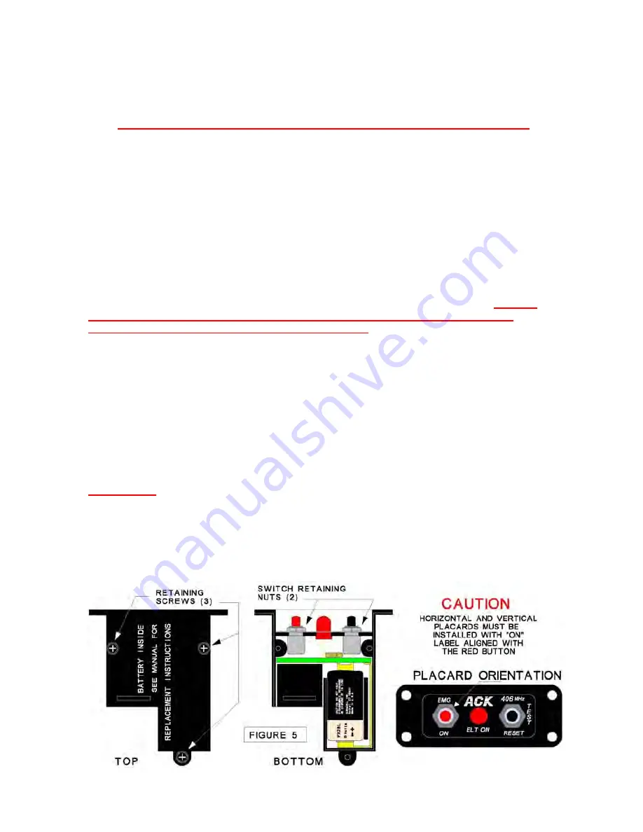
1.) Remove the three retaining screws which secure the top and bottom half of the RCPI
unit. (Fig. 5)
2.) Remove the two switch retaining nuts located on the face of the RCPI. There are two
placards supplied with the remote, (a horizontal, and a vertical) remove the protective
plastic film from the placard face, and install the vertical or horizontal placard.
Caution:
The “ON“ position marking on the placard must be aligned with the red switch, the
“TEST/RESET” marking must be over the black switch
(Fig. 5)
3.) Carefully remove the top half of the RCPI unit exposing the battery compartment. (Fig.
5) if replacing an old battery, carefully inspect the battery contacts for dirt or corrosion. If
the contacts need cleaning, use only non abrasive electrical contact cleaner and a stiff
brush. Abrasive cleaners will remove the nickel and gold plating from contacts.
4.) Insert the battery with the polarity as shown in figure 5. The polarity is also engraved on
the bottom of the battery compartment.
5.) Replace the top half of the RCPI, and replace the three retaining screws, and two
retaining nuts on the face of the RCPI.
6.) The next RCPI battery replacement date should be recorded in the aircraft log book with
a note indicating the battery expiration dates.
IMPORTANT:
The RCPI must be mounted so that it can be seen, and operated by the pilot
of the aircraft from a normal operating position. We strongly recommend that the RCPI be
located within an area that is part of the pilots regular instrument scan.
5.) Mount the RCPI using four 4-40 screws, and nuts. Figure 6 shows the dimensions of the
cut out for the RCPI unit. If the unit is to be mounted in a location that does not have a
flush mounting surface (i.e. Beneath the panel glare shield.) an angle bracket should be
fabricated. (Fig. 6)
5
For a list of other approved antennas and other technical information visit our web site .
WWW.ACKAVIONICS.COM
Содержание E-04
Страница 16: ...16 SECTION 16 MAJOR PARTS ...
Страница 17: ...17 SECTION 17 DO 160F ED 14F ENVIRONMENTAL CATEGORIES ...


