ACK! E-04 Скачать руководство пользователя страница 9

2.) The RCPI unit is connected to the ELT transmitter via a RJ-11 standard type modular 
connectors. A 15 foot connecting cable is included with each ELT. To install the cable 
connect the modular plug on the ELT transmitter into the jack end of the interconnecting 
cable. Run the plug end of the cable to the audio alert unit. Run the short audio alert cable 
from the RCPI to the audio alert module (page 6 Fig. 8)  avoid running this cable near 
sources of strong EMI/RFI radiation. (i.e. Comm cables, strobe light power cables, starter 
cables.) Secure the cable along its run using tie wraps, or other suitable methods. The 
interconnecting cable may be shortened, or a longer cable of up to 150ft. may be used if 
necessary. After connecting the mini DIN RS 232 jack and plug. Wrap electrical tape 
around the joint at the center of the connection to secure the two parts together, and seal 
the joint from moisture. (Page 8 Fig. 12.5) 


3.) After installation, and wiring is complete, verify that the ELT is receiving and 
processing GPS data correctly. Apply power to both the ELT, and the GPS equipment 
supplying data. Make sure the GPS has a satellite fix, and is reporting position data. 
Fabricate a GPS verification tool as shown in figure 14.


4.) Connect the test tool as shown in Fig 14. The main switch on the ELT should be in the 
“armed” position.  


5.) With power supplied both to the ELT, and the GPS, make sure the GPS has acquired the 
satellites, and is transmitting valid position data. The LED should blink each time the ELT 
receives a valid GPS data position. (Typically once per second) This test verifies that the 
ELT is properly receiving, and processing position data from the GPS system. This is a 
very short duration low intensity flash make sure the LED is shielded from bright light. 


6.) After verifying that the ELT is receiving, and processing GPS data correctly. Seal the 
end of the GPS verification test line using a adhesive lined end cap, (McMaster-Carr 
72855k21) or other method to protect it from moisture. Secure the test wire to the shielded 
cable with a tie wrap.  


7.) Complete the steps in section 8 (registration) before you verify the installed operation 
of the ELT. After you have registered the ELT, do the self test as described in section 9 to 
verify the complete system is functioning properly.  


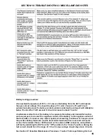
8.) Record the ELT battery expiration date marked on the ELT battery case, the expiration 
of the RCPI, and audio alert batteries in the airframe logbook.


SECTION 8 REGISTRATION 

1.) Before completing the final check out of the ELT, 

YOU MUST FIRST REGISTER YOUR 

BEACON FOLLOWING THE REGISTRATION REQUIREMENTS OF THE COUNTRY WHERE 
THE AIRCRAFT IS BASED. YOU CAN ONLY REGISTER THE ELT IN THE COUNTRY THE 
AIRCRAFT IS REGISTERED. 


2.)


There is a preprinted self adhesive label supplied with the ELT that has the hex code, 

manufacturer, and model number on it which you should affix to the top of the registration 
form. Or you can refer to this label when registering over the internet. You can download the 
registration forms for your country from our website. 


WWW.ACKAVIONICS.COM 


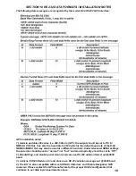
3.) In the U.S. and Canada you can mail or fax the registration forms, however it is strongly 
recommend that beacon registration be completed on line  at the following sites: 

Содержание E-04

Страница 1: ... DESIRING TO INSTALL THIS ARTICLE ON A SPECIFIC TYPE OR CLASS OF AIRCRAFT TO DETERMINE THAT THE AIRCRAFT INSTALLATION CONDITIONS ARE WITHIN THE TSO STANDARDS THE ARTICLE MAY BE INSTALLED ONLY IF FURTHER EVALUATION BY THE APPLICANT DOCUMENTS AN ACCEPTABLE INSTALLATION AND IT IS APPROVED BY THE ADMINISTRATOR P N E04M REV DATE 12 02 2015 Rev 1 8 PRINTED IN THE USA APPROVALS FAA TRANSPORT CANADA TSO C...

Страница 2: ...0 minutes or less with an accuracy of about 300 feet The model E 04 ELT may be installed without interfacing it to the aircraft GPS system however we strongly recommend that when available the GPS data be supplied to the ELT For aircraft which do not have GPS data available the unit can be interfaced with a low cost GPS data receiver such as the Garmin GPS 18PC which is available for less than 75 ...

Страница 3: ... pointed in the normal direction of forward flight The longitudinal axis should be aligned within 10 degrees of the longitudinal axis horizontally and at a 45 degree downward angle as shown in Fig 2 3 SECTION 3 ANTENNA INSTALLATION In order to meet the requirements of COSPAS SARSAT TSO C 126b TSO C 91a and FAR 91 207 an approved antenna must be used The antenna supplied with the ELT P N E 04 8 is ...

Страница 4: ... airframe a supplementary ground plane must be installed The supplemental ground plane must have a minimum diameter of 24 however 48 will provide maximum power at 121 5 MHz and is recommended The ground plane must be centered around the base of the antenna This may be fabricated out of copper or aluminum tape The tape should be cut into six ele ments 12 long and the tape elements should be evenly ...

Страница 5: ...g 5 3 Carefully remove the top half of the RCPI unit exposing the battery compartment Fig 5 if replacing an old battery carefully inspect the battery contacts for dirt or corrosion If the contacts need cleaning use only non abrasive electrical contact cleaner and a stiff brush Abrasive cleaners will remove the nickel and gold plating from contacts 4 Insert the battery with the polarity as shown in...

Страница 6: ...ver to the audio alert indicator P N E 04 7 Install a Duracell CR 2 3 volt or equivalent battery Make sure to observe the battery polarity Fig 7 Replace the top cover making sure the grill portion of the indicator cover is positioned over the buzzer The battery must be replaced every 10 years The expiration date must be entered in the aircraft airframe log book ...

Страница 7: ...fourth pin is used to verify the ELT is receiving and processing the data properly after installing the ELT A three conductor shielded cable 24 AWG or heaver Aircraft Spruce P N 11 04478 or equivalent should be used to connect the ELT RS 232 data and power to the aircraft systems Figure 11 shows the pin outs for RS 232 and power input 1 Disassemble the mini DIN connector noting the position of the...

Страница 8: ...ase If possible the cable should not cross any production breaks in the airframe and must have a reasonable amount of slack at the transmitter The slack is necessary for easy removal of the coaxial cable during maintenance If a longer cable than the one supplied with the unit 5 foot is needed it may be fabricated using RG 58 cable or equivalent and Amp 227079 5 connectors or their equivalent Inser...

Страница 9: ...s a valid GPS data position Typically once per second This test verifies that the ELT is properly receiving and processing position data from the GPS system This is a very short duration low intensity flash make sure the LED is shielded from bright light 6 After verifying that the ELT is receiving and processing GPS data correctly Seal the end of the GPS verification test line using a adhesive lin...

Страница 10: ...tch on the ELT SHOULD BE LEFT OFF AT ALL TIMES EXCEPT WHEN THE ELT IS IN THE ARMED POSITION The cover has a center cone that projects down into the switch recess and provides for positive retention of the switch in the armed position There are two modes in which the ELT may be deactivated 1 Pressing the Reset button on the remote control RCPI Page 11 Fig 16 2 Placing the main switch on the ELT in ...

Страница 11: ...condition The ELT will not be disabled but it should be inspected by a qualified avionics facility as soon as possible The trouble code returns a series of beeps with a two second delay and then the trouble code is repeated one more time The first beeps alert you that there is a trouble condition The two second delay is to allow you to be ready to count the second set of beeps Trouble code sequenc...

Страница 12: ...G 3 7 Reinstall the ELT make sure the cables are secured and properly connected Make sure to seal the din connector if the ELT is connected to the aircraft GPS Page 8 Fig 12 5 Place the main switch in the Armed position and install the rubber cover over the main switch opening 3 8 Perform the self test described in section 9 to verify proper operation BATTERY AND ELT DOT IATA SHIPPING INFORMATION ...

Страница 13: ... 13 WARRANTY PROCEDURE Should it become necessary to return the ELT for warranty service REMOVE THE ELT BATTERY BEFORE SHIPPING THE UNIT TO OUR FACILITY The battery is DOT IATA CLASS 9 HAZARDOUS MATERIAL and DOT IATA regulations must be followed whenever shipping the battery or ELT and battery See section 11 page 12 for additional shipping information All units must be returned to our facility fre...

Страница 14: ... airworthiness We strongly recommend the WS technologies inc BT100av or BT100avs tester be used to verify the performance characteristics of the ELT WEBSITE WWW WST CA THESE TESTS SHOULD ONLY BE PREFORMED IN A RF SCREEN ROOM When using conventional test equipment to perform this test Connect the RF output of the ELT to a spectrum analyzer with a 50 ohm impedance capable of measuring frequency powe...

Страница 15: ...E 50 OHM NOMINAL VSWR 121 5 MHz 2 5 1 VSWR 406 MHz 1 5 1 MAX 260 KNOTS SEA LEVEL BATTERY PART NUMBER E 04 0 APPROVALS FAA TRANSPORT CANADA TSO C 142a ETSO C 142a BRAZIL ANAC TYPE Li SO2 NON FLAMMABLE ELECTROLYTE VOLTAGE 12 VOLTS OPERATING TEMPERATURE 20C TO 55C DIMENSIONS 5 750 x 2 850 x 2 850 146mm x 72mm x 72mm WEIGHT 1 18 lbs 535 kg AMP HOUR RATING 7 75 Ah NON RECHARGEABLE LITHIUM CONTENT 9 8 G...

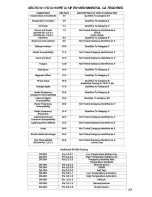
Страница 16: ...16 SECTION 16 MAJOR PARTS ...

Страница 17: ...17 SECTION 17 DO 160F ED 14F ENVIRONMENTAL CATEGORIES ...

Страница 18: ...ut may also be used at a different baud rate Under advanced NEMA settings the data rate should be set to normal not fast and Garmin priority should be set to Off 2 Bendix King and Garmin panel mount receivers use RS 232 aviation format out 9600 baud 3 Avidyne IFD540 Revision 9 3 and above use RS 232 aviation message out 9600 baud 4 The ELT is also compatible with most ARNAV II Morrow and Trimble N...

Страница 19: ...o separate the battery and transmitter section and use jumpers to connect the negative contact of the battery to the negative contact of the transmitter Connect an amp meter capable of measuring a minimum of 3 amps across the positive battery terminals and the transmitter terminals Place a second volt meter across the terminals Place a 50 Ohm load on the antenna BNC connector and perform a self te...

Страница 20: ...G FACILITY THIS WARRANTY DOES NOT INCLUDE REPAIR OR REPLACEMENT OF ANY PART THAT HAS BEEN IMPROPERLY USED INSTALLED OR PHYSICALLY DAMAGED THIS WARRANTY DOES NOT COVER ANY DAMAGE CAUSED BY CHEMICAL EXPOSURE TO THE ELT DISCHARGE OF THE LITHIUM BATTERY IS NOT COVERED BY THIS OR ANY OTHER WARRANTY EXCEPT AS PROVIDED HEREIN ACK TECHNOLOGIES INC MAKES NO EXPRESS WARRANTIES AND ANY IMPLEMENTED WARRANTY O...

Отзывы: