Chapter 5
81
Top View
NOTE:
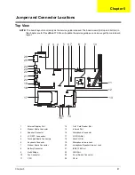
The board layout is not ready as the service guide released. The board views (bot top and bottom) in
this chapter are for TravelMate 370. We will update the service guide as soon as we get the main board
layout.
1
External Display Port
14
3-in1 Card Reader Slot
2
Modem Cable Connector
15
Infrared Port
3
Speaker Connector
16
Microphone Connector
4
LCD FPC Connectors
17
PCMCIA Slot
5
Touchpad Board Connectors
18
Mini-PCI Slot
6
Keyboard Connector
19
Microphone/Line-in Jack
7
Modem Board Connector
20
Headphone/Speaker/Line-out Jack
8
Battery Connector
21
IEEE 1394 Port
9
North Bridge
22
USB Port
10
Fan Connector
23
Cover Switch Connector
11
CPU
24
DC-In
1
2 3 4
5 6 7
9
10
12
13
14
15
16
17
18
19
20
21
22
23
24
26
8
11
25
Jumper and Connector Locations
Chapter 5
Содержание TravelMate 380 series
Страница 6: ...VI ...
Страница 50: ...44 Chapter 3 ...
Страница 51: ...Chapter 3 45 Removing the Battery 1 Slide the two battery latches 2 Then remove the battery ...
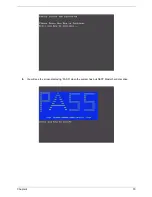
Страница 85: ...Chapter 4 79 8 You will see the screen displaying PASS when the system has buit NAPP Master hard disc drive ...
Страница 86: ...80 Chapter 4 ...
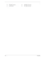
Страница 88: ...82 Chapter 5 12 RTC Battery Connector 25 RJ45 Ethernet Connector 13 HDD Connector 26 RJ11 Modem Connector ...
Страница 91: ...84 Chapter 6 Exploded Diagram The Unit ...
Страница 100: ...Chapter 6 93 ...
Страница 107: ...100 Appendix C ...

