


Chapter 2
25
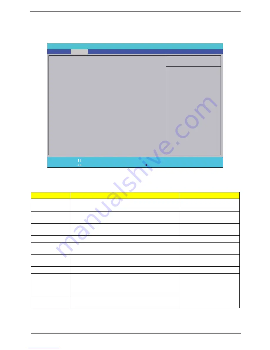
Main
The Main screen allows the user to set the system time and date as well as enable and disable boot option
and recovery.
NOTE:
The screen above is for your reference only. Actual values may differ.
The table below describes the parameters in this screen. Settings in
boldface
are the default and suggested
parameter settings.
Parameter
Description
Format/Option
System Time
Sets the system time. The hours are displayed with 24-
hour format.
Format: HH:MM:SS
(hour:minute:second)
System Date
Sets the system date.
Format MM/DD/YYYY
(month/day/year)
Total Memory
This field reports the memory size of the system.
Memory size is fixed to 4094MB.
N/A
Video Memory
Shows the video memory size.
N/A
Quiet Boot
Allows startup to skip certain tests while booting,
decreasing the time needed to boot the system.
Option:
Enabled
or Disabled
Network Boot
Enables, disables the system boot from LAN (remote
server).
Option:
Enabled
or Disabled
F12 Boot Menu
Enables, disables Boot Menu during POST.
Option: Enabled or
Disabled
D2D Recovery
Enables, disables D2D Recovery function. The function
allows the user to create a hidden partition on hard disc
drive to store operation system and restore the system
to factory defaults.
Option:
Enabled
or Disabled
SATA Mode
Control the mode in which the SATA controller should
operate.
Option:
AHCI
or IDE
Item Specific Help
<Tab>, <Shift-Tab>, or
<Enter> selects field.
F1
ESC
Help
Exit
Select Item
Select Menu
Change Values
Select
SubMenu
Enter
F9
F10
Setup Default
Save and Exit
[10:49:59]
[03/03/2009]
4094 MB
512 MB
[Enabled]
[Enabled]
[Disabled]
[Enabled]
[AHCI Mode]
[10:
49:59]
[03/03/2009]
4094 MB
512 MB
[Enabled]
[Enabled]
[Disabled]
[Enabled]
[AHCI Mode]
System Time:
System Date:
Total Memory:
Video Memory:
Quiet Boot
Network Boot
F12 Boot Menu
D2D Recovery
SATA Mode
System Time:
System Date:
Total Memory:
Video Memory:
Quiet Boot
Network Boot
F12 Boot Menu
D2D Recovery
SATA Mode
F5/F6
Phoenix SecureCode(tm) Setup Utility
Boot
Exit
Security
Information
Power
Main
Содержание Extensa 5635
Страница 2: ...II PRINTED IN TAIWAN ...
Страница 10: ...X Table of Contents ...
Страница 62: ...52 Chapter 3 4 Detach the WLAN Module from the WLAN socket ...
Страница 90: ...80 Chapter 3 4 Lift up the Bezel and remove it from the LCD Module ...
Страница 92: ...82 Chapter 3 4 Disconnect the Camera cable and remove the LCD Panel ...
Страница 98: ...88 Chapter 3 IMPORTANT Ensure that the LCD Cable runs as shown to avoid trapping when the Bezel is replaced ...
Страница 120: ...110 Chapter 4 ...
Страница 137: ...Chapter 6 127 ...
Страница 188: ...Appendix A 178 ...
Страница 194: ...184 Appendix B ...
Страница 196: ...186 Appendix C ...
Страница 200: ...190 ...


