Chapter 1
9
Indicators
The computer has several easy-to-read status indicators:
The front panel indicators are visible even when the computer cover is closed.
NOTE:
1.
Charging:
The light shows amber when the battery is charging. 2.
Fully charged:
The light shows
green when in AC mode.
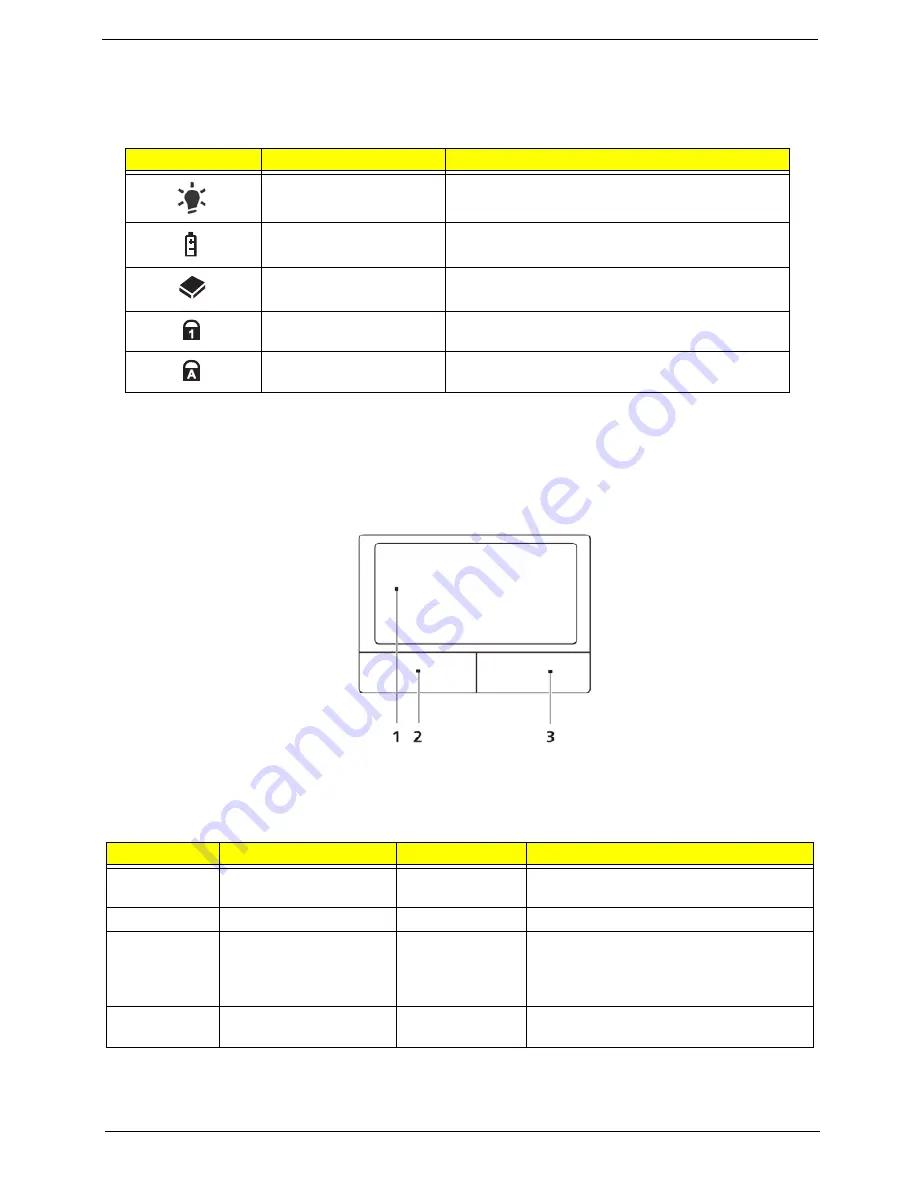
TouchPad Basics
The following items show you how to use the TouchPad:
•
Move your finger across the TouchPad (1) to move the cursor.
•
Press the left (2) and right (3) buttons located beneath the TouchPad to perform selection and execution
functions. These two buttons are similar to the left and right buttons on a mouse. Tapping on the TouchPad is
the same as clicking the left button.
NOTE:
When using the TouchPad, keep it - and your fingers - dry and clean. The TouchPad is sensitive to
finger movement; hence, the lighter the touch, the better the response. Tapping too hard will not
increase the TouchPad’s responsiveness.
Icon
Function
Description
Power
Indicates the computer's power status.
Battery
Indicates the computer's battery status.
HDD
Indicates when the hard disk drive is active.
Num Lock
Lights up when Num Lock is activated.
Caps Lock
Lights up when Caps Lock is activated.
Function
Left Button (1)
Right Button (3)
Main TouchPad (2)
Execute
Quickly click twice.
Tap twice (at the same speed as double-
clicking a mouse button).
Select
Click once.
Tap once.
Drag
Click and hold, then use
finger on the TouchPad
to drag the cursor.
Tap twice (at the same speed as double-
clicking a mouse button); rest your finger
on the TouchPad on the second tap and
drag the cursor.
Access
context menu
Click once.
Содержание eMachines E720 Series
Страница 6: ...VI...
Страница 60: ...50 Chapter 3 6 Remove the HDD cover as shown 7 Remove the WLAN cover as shown...
Страница 81: ...Chapter 3 71 6 Turn the upper cover over The upper cover appears as follows...
Страница 102: ...92 Chapter 3 7 Lift the Thermal Module clear of the Mainboard...
Страница 108: ...98 Chapter 3 6 Disconnect the left and right Inverter board cables as shown...
Страница 122: ...112 Chapter 3 3 Replace the RJ 11 cable in its housing...
Страница 133: ...Chapter 3 123 2 Replace the bracket as shown 3 Replace the single securing screw...
Страница 136: ...126 Chapter 3 2 Connect the seven cables on the mainboard as shown B C D E F G A...
Страница 142: ...132 Chapter 3 7 Replace the adhesive strip to secure the cable 8 Replace bracket and secure with provided screw...
Страница 148: ...138 Chapter 3...
Страница 170: ...160 Chapter 4...
Страница 188: ...Appendix A 178 Model Definition and Configuration Appendix A...
Страница 206: ...Appendix A 196...
Страница 212: ...202 Appendix C...


