


21
Chapter 2
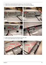
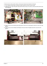
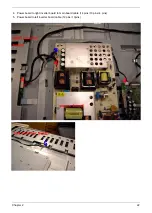
Board and Cable Placement
Please refer to this section to reconnect all cables when you do the assembly.
1. LVDS cable
2. Power board to main board to I/O board cable (14 pins/ 10 pins/ 8 pins)
3. Speaker cables: red/blace cable connected to right speaker, white/black connected to left speaker
Содержание AT4230C
Страница 10: ...4 Chapter 1 LCD Main Board Block Diagram ...
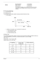
Страница 29: ...23 Chapter 2 6 Audio to main board cable 8 pins 7pins ...
Страница 35: ...Chapter 3 29 DDC POP PIP Fails 4 Main Board END Replacement N G ...
Страница 38: ...32 Chapter 3 Unit Hang Up Suddenly 8 Power Board Main Board END Replacement Replacement N G N G ...
Страница 41: ...Chapter 3 35 VGA No Display 11 VGA Cable EDID CODE END Replacement Write EDID N G N G MB Replacement N G ...
Страница 51: ......


