Chapter 2
16
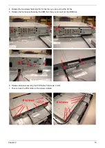
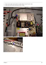
4. Release the two screws fastening the I/O box then you can pull out the I/O box.
5. Release the four screws fastening the HDMI box then you can pull out the HDMI box.
6. Release all screws securing the PCB holder,
14
screws in total.
7. Then remove the PCB holder as the arrows indicate.
Содержание AT4230C
Страница 10: ...4 Chapter 1 LCD Main Board Block Diagram ...
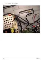
Страница 29: ...23 Chapter 2 6 Audio to main board cable 8 pins 7pins ...
Страница 35: ...Chapter 3 29 DDC POP PIP Fails 4 Main Board END Replacement N G ...
Страница 38: ...32 Chapter 3 Unit Hang Up Suddenly 8 Power Board Main Board END Replacement Replacement N G N G ...
Страница 41: ...Chapter 3 35 VGA No Display 11 VGA Cable EDID CODE END Replacement Write EDID N G N G MB Replacement N G ...
Страница 51: ......


