4-12
Troubleshooting
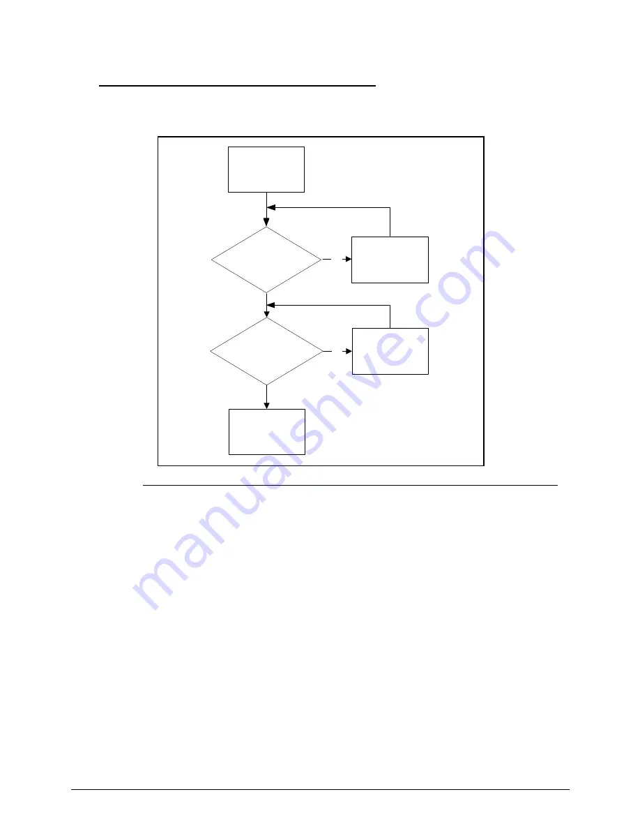
Microphone Failure
0
If internal or external Microphones fail, perform the following, one at a time.
Figure 4-7.
Microphone Failure
1. Check that the microphone is enabled. Navigate to
Start-> Control Panel->Hardware and
Sound-> Sound
and select the Recording tab.
2. Right click on the Recording tab and select
Show Disabled Devices (clear by default)
. The
microphone appears on the Recording tab.
3. Right click on the microphone and select Enable.
4. Select the microphone then click Properties. Select the Levels tab.
5. Increase the volume to the maximum setting and click OK.
6. Test the microphone hardware:
Select the microphone and click Configure.
Select Set up microphone.
Select the microphone type from the list and click Next.
Follow the on-screen prompts to complete the test.
7. If the Issue is still not resolved, refer to
Online Support Information
.
Start
No
Check Mic to
MB cable well
connected?
Re-assemble Mic
cable to MB
No
Check Mic module?
Swap Mic module
and cable
Replace M/B
Содержание Aspire M3-581T
Страница 1: ...Acer M3 581T 581TG SERVICEGUIDE...
Страница 4: ...iv...
Страница 9: ...v...
Страница 10: ...vi...
Страница 11: ...CHAPTER 1 Hardware Specifications...
Страница 14: ...1 4...
Страница 32: ...1 22 Hardware Specifications and Configurations System Block Diagram...
Страница 50: ...1 40 Hardware Specifications and Configurations...
Страница 51: ...CHAPTER 2 System Utilities...
Страница 61: ...System Utilities 2 11 Figure 2 9 Setup Warning...
Страница 76: ...2 26 System Utilities 5 Execute RU bat to read SMBIOS Type 1 UUID Figure 2 27 Figure 2 28 Read UUID...
Страница 77: ...System Utilities 2 27 6 Execute WU bat to write SMBIOS Type 1 UUID Figure 2 28 Figure 2 29 Write UUID...
Страница 82: ...2 32 System Utilities 12 Key in x key to save and exit configuration Figure 2 36 Exit configuration...
Страница 83: ...System Utilities 2 33 13 Key in q to exit Broadcom program Figure 2 37 Exit Broadcom program...
Страница 84: ...2 34 System Utilities...
Страница 85: ...CHAPTER 3 Machine Maintenance...
Страница 88: ...3 4...
Страница 99: ...3 15 3 Pull the WLAN module out and away Figure 3 14 WLAN Module...
Страница 102: ...3 18 5 Pry the ODD bezel off the ODD module Figure 3 19 ODD Bezel...
Страница 109: ...3 25 11 Remove the keyboard from the top case Figure 3 31 Keyboard module...
Страница 112: ...3 28 Figure 3 37 Battery module...
Страница 121: ...3 37 3 Lift the thermal module and take it away Figure 3 54 Thermal Module...
Страница 122: ...3 38 Removing the Bluetooth Board 0 1 Lift the bluetooth and move it away Figure 3 55 Bluetooth Board...
Страница 124: ...3 40 3 Remove the speakers and cable Figure 3 58 Speakers...
Страница 129: ...3 45 Figure 3 67 LCD Bezel...
Страница 135: ...3 51 Figure 3 78 LCD Panel Table 3 19 Screws Step Screw Quantity Screw Type LCD Panel Assembly M2 2 5 4...
Страница 136: ...3 52 Replacing the LCD Bezel 0 1 Place the bezel onto the LCD module Figure 3 79 LCD Bezel Figure 3 80 LCD Bezel...
Страница 137: ...3 53 Replacing the Bluetooth 0 1 Place the Bluetooth into the socket Figure 3 81 Bluetooth...
Страница 166: ...3 82 Replacing the Dummy Card 0 1 Insert the Dummy card in until it clicks into place Figure 3 135 Dummy Card...
Страница 167: ...CHAPTER 4 Troubleshooting...
Страница 194: ...4 28 Troubleshooting...
Страница 195: ...CHAPTER 5 Jumper and Connector Locations...
Страница 203: ...CHAPTER 6 FRU List...
Страница 222: ...6 20 FRU Field Replaceable Unit List...
Страница 223: ...CHAPTER 7 Test Compatible Components...
Страница 224: ...8 2 Microsoft Windows 7 Environment Test 7 4 M3 581T 581TG 7 4...
Страница 230: ...7 8 Test Compatible Components...
Страница 231: ...CHAPTER 8 Online Support Information...
Страница 232: ...9 2 Introduction 8 3...
Страница 234: ...8 4 Online Support Information...


