3-44
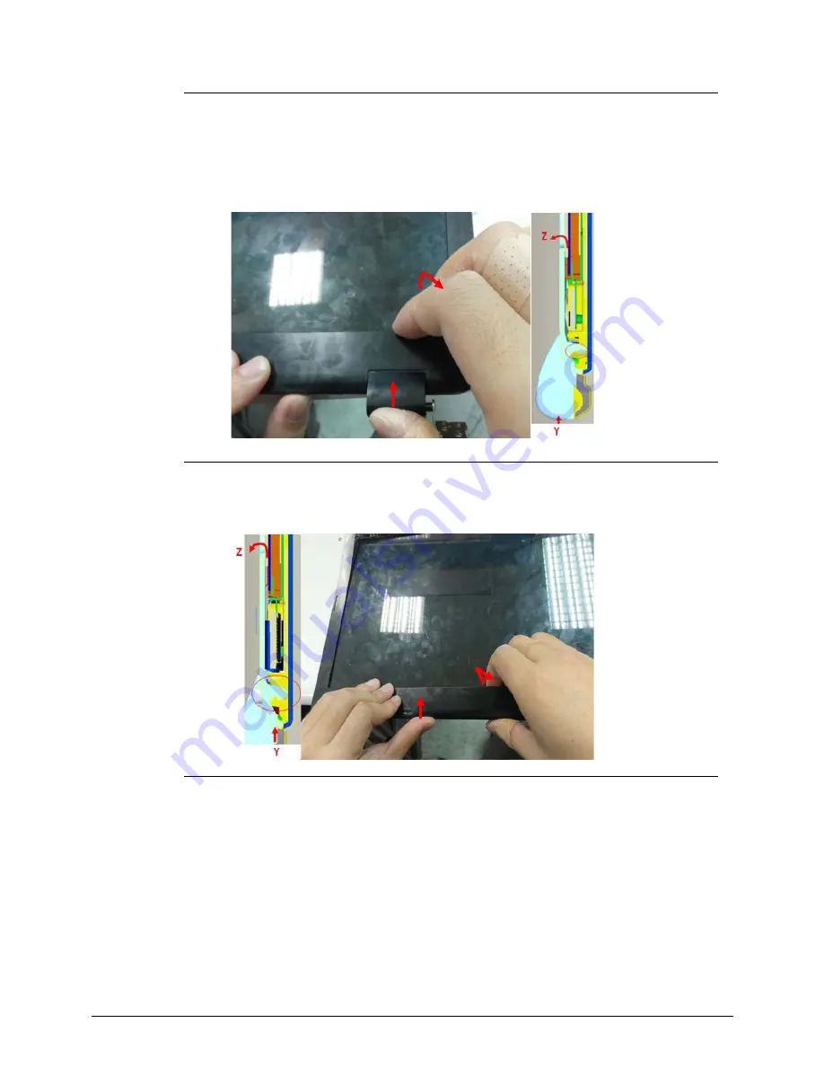
Figure 3-64.
LCD Bezel
6. Press center area of the bottom edge with left fingers, then push the edge of the hinge cap
with thumb of the right hand in +Y direction, and apply force with index finger and middle
finger in +Z direction.
Figure 3-65.
LCD Bezel
7. 3-2 Repeat 3-1 and disengage the latches one at a time, from right side all the way to the
left.
Figure 3-66.
LCD Bezel
8. Take LCD bezel away.
Содержание Aspire M3-581T
Страница 1: ...Acer M3 581T 581TG SERVICEGUIDE...
Страница 4: ...iv...
Страница 9: ...v...
Страница 10: ...vi...
Страница 11: ...CHAPTER 1 Hardware Specifications...
Страница 14: ...1 4...
Страница 32: ...1 22 Hardware Specifications and Configurations System Block Diagram...
Страница 50: ...1 40 Hardware Specifications and Configurations...
Страница 51: ...CHAPTER 2 System Utilities...
Страница 61: ...System Utilities 2 11 Figure 2 9 Setup Warning...
Страница 76: ...2 26 System Utilities 5 Execute RU bat to read SMBIOS Type 1 UUID Figure 2 27 Figure 2 28 Read UUID...
Страница 77: ...System Utilities 2 27 6 Execute WU bat to write SMBIOS Type 1 UUID Figure 2 28 Figure 2 29 Write UUID...
Страница 82: ...2 32 System Utilities 12 Key in x key to save and exit configuration Figure 2 36 Exit configuration...
Страница 83: ...System Utilities 2 33 13 Key in q to exit Broadcom program Figure 2 37 Exit Broadcom program...
Страница 84: ...2 34 System Utilities...
Страница 85: ...CHAPTER 3 Machine Maintenance...
Страница 88: ...3 4...
Страница 99: ...3 15 3 Pull the WLAN module out and away Figure 3 14 WLAN Module...
Страница 102: ...3 18 5 Pry the ODD bezel off the ODD module Figure 3 19 ODD Bezel...
Страница 109: ...3 25 11 Remove the keyboard from the top case Figure 3 31 Keyboard module...
Страница 112: ...3 28 Figure 3 37 Battery module...
Страница 121: ...3 37 3 Lift the thermal module and take it away Figure 3 54 Thermal Module...
Страница 122: ...3 38 Removing the Bluetooth Board 0 1 Lift the bluetooth and move it away Figure 3 55 Bluetooth Board...
Страница 124: ...3 40 3 Remove the speakers and cable Figure 3 58 Speakers...
Страница 129: ...3 45 Figure 3 67 LCD Bezel...
Страница 135: ...3 51 Figure 3 78 LCD Panel Table 3 19 Screws Step Screw Quantity Screw Type LCD Panel Assembly M2 2 5 4...
Страница 136: ...3 52 Replacing the LCD Bezel 0 1 Place the bezel onto the LCD module Figure 3 79 LCD Bezel Figure 3 80 LCD Bezel...
Страница 137: ...3 53 Replacing the Bluetooth 0 1 Place the Bluetooth into the socket Figure 3 81 Bluetooth...
Страница 166: ...3 82 Replacing the Dummy Card 0 1 Insert the Dummy card in until it clicks into place Figure 3 135 Dummy Card...
Страница 167: ...CHAPTER 4 Troubleshooting...
Страница 194: ...4 28 Troubleshooting...
Страница 195: ...CHAPTER 5 Jumper and Connector Locations...
Страница 203: ...CHAPTER 6 FRU List...
Страница 222: ...6 20 FRU Field Replaceable Unit List...
Страница 223: ...CHAPTER 7 Test Compatible Components...
Страница 224: ...8 2 Microsoft Windows 7 Environment Test 7 4 M3 581T 581TG 7 4...
Страница 230: ...7 8 Test Compatible Components...
Страница 231: ...CHAPTER 8 Online Support Information...
Страница 232: ...9 2 Introduction 8 3...
Страница 234: ...8 4 Online Support Information...


