


Chapter 2
41
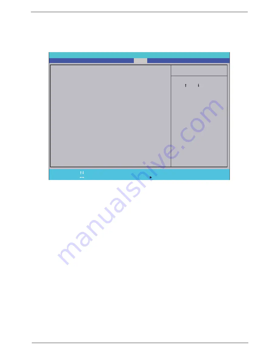
Boot
This menu allows the user to decide the order of boot devices to load the operating system. Bootable devices
includes the USB diskette drives, the onboard hard disk drive and the DVD drive in the module bay.
Select Boot Devices to select specific devices to support boot.
I t e m S p e c i f i c H e l p
U s e < > o r < > t o s e l e c t
a d e v i c e , t h e n p r e s s
< F 5 > t o m o v e i t d o w n t h e
l i s t , o r < F 6 > t o m o v e
i t u p t h e l i s t . P r e s s
< E s c > t o e s c a p e t h e m e n u
F 1
E S C
H e l p
E x i t
S e l e c t I t e m
S e l e c t M e n u
C h a n g e Va l u e s
S e l e c t
S u b M e n u
E n t e r
F 9
F 1 0
S e t u p D e f a u l t
S a v e a n d E x i t
B o o t p r i o r i t y o r d e r :
1 . I D E H D D : T o s h i b a M K 5 0 5 5 G S X - ( S 1 )
2 . I D E H D D : W D C W D 1 6 0 0 B E V T - 2 2 Z C T 0 - ( S 5 )
3 . I D E C D : H L - D T - S T D V D R A M G T 2 0 N - ( S 2 )
4 . P C I L A N : M B A v 1 1 . 4 . 1 S l o t 0 6 0 0
5 . U S B H D D :
6 . U S B C D R O M :
7 . U S B F D C :
8 . U S B K E Y :
F 5 / F 6
P h o e n i x S e c u r e C o r e ( t m ) S e t u p U t i l i t y
Main
Boot
Exit
Security
Information
E x c l u d e d f r o m b o o t o r d e r :
E x c l u d e d f r o m b o o t o r d e r :
Содержание Aspire 8935G
Страница 6: ...VI ...
Страница 44: ...34 Chapter 1 ...
Страница 62: ...52 Chapter 2 ...
Страница 78: ...68 Chapter 3 4 Remove the TV Tuner as shown ...
Страница 80: ...70 Chapter 3 4 Detach the WLAN Module from the WLAN socket ...
Страница 94: ...84 Chapter 3 10 Remove the Upper Cover as shown Upper Cover green callout M2 3 1 Step Size Quantity Screw Type ...
Страница 97: ...Chapter 3 87 5 Lift the board clear of the Upper Cover ...
Страница 100: ...90 Chapter 3 5 Lift the Media Board clear of the Upper Cover ...
Страница 106: ...96 Chapter 3 8 Lift the board clear of the Upper Cover ...
Страница 109: ...Chapter 3 99 5 Remove the Bluetooth Board from the Lower Cover ...
Страница 118: ...108 Chapter 3 4 Using both hands lift the Subwoofer clear of the Lower Cover ...
Страница 155: ...Chapter 3 145 3 Press down around the perimeter of the bezel to secure it in place ...
Страница 165: ...Chapter 3 155 3 Insert the Subwoofer cable into the cable channel Ensure that the cable passes under all cable clips ...
Страница 173: ...Chapter 3 163 4 Connect the Bluetooth cable to the Mainboard ...
Страница 184: ...174 Chapter 3 4 Connect the Volume Control FFC to the Media Board and close the locking latch ...
Страница 195: ...Chapter 3 185 Step Size Quantity Screw Type Switch Cover red callout M2 5 6 5 9 Switch Cover green callout M2 5 4 4 ...
Страница 202: ...192 Chapter 3 2 Tighten the seven captive screws in the Lower Door ...
Страница 204: ...194 Chapter 3 ...
Страница 239: ...Chapter 6 229 ...
Страница 316: ...306 Appendix C ...
Страница 320: ...310 ...


