


Chapter 1
19
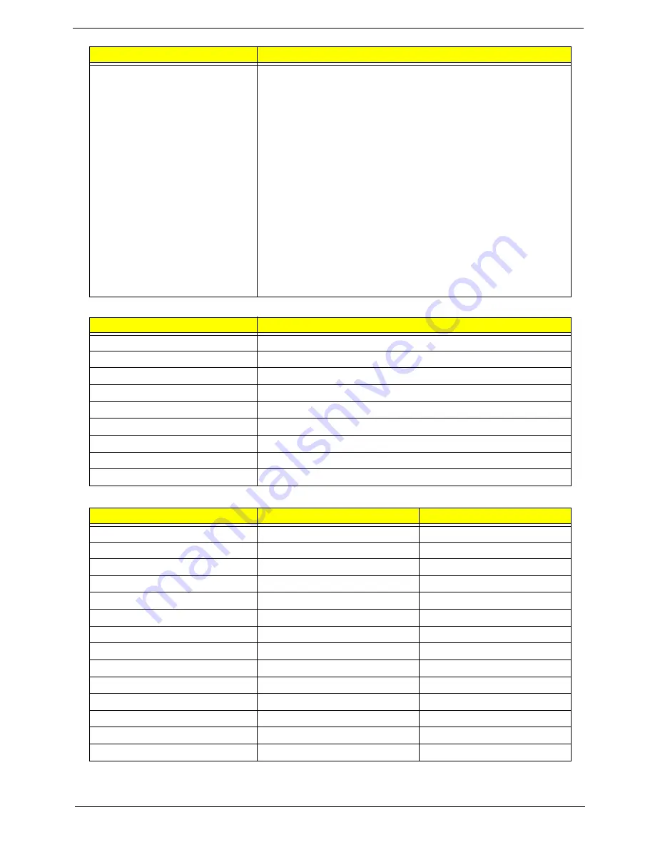
System Memory
Memory Combinations
NOTE:
Above table lists some system memory configurations. You may combine DIMMs with various capacities to
form other combinations. On above table, the configuration of slot 1 and slot 2 could be reversed.
Features
•
Flash ROM 1MB
•
Support ISIPP
•
Support Acer UI
•
Support multi-boot
•
Suspend to RAM (S3)/Disk (S4)
•
Various hot-keys for system control
•
Support SMBUS 2.0, PCI2.3
•
ACPI 2.0 compliance with Intel Speed Step Support C1, C2,
C3, C4,C6 and S3, S4 for mobile CPU
•
DMI utility for BIOS serial number configurable/asset tag
•
Support PXE
•
Support Y2K solution
•
Support Win Flash Wake on LAN from S3
•
Wake on LAN form S4 in AC mode
•
System information
Item
Specification
Memory controller
Intel Cantiga with ICH9M
Memory size
2GB
DIMM socket number
2
Supports memory size per socket
2GB
Supports maximum memory size
4GB
Supports DIMM type
DDRIII
Supports DIMM Speed
667/800/1066 MHz
Supports DIMM voltage
1.5V
Cache
4MB L2
Slot 1
Slot 2
Total Memory
0MB
512MB
512MB
0MB
1024MB
1024MB
0MB
2048MB
2048MB
512MB
512MB
1024MB
512MB
1024MB
1536MB
512MB
2048MB
2560MB
1024MB
0MB
1024MB
1024MB
512MB
1536MB
1024MB
1024MB
2048MB
1024MB
2048MB
3072MB
2048MB
0MB
2048MB
2048MB
512MB
2560MB
2048MB
1024MB
3072MB
2048MB
2048MB
4096MB
Item
Specification
Содержание Aspire 8935G
Страница 6: ...VI ...
Страница 44: ...34 Chapter 1 ...
Страница 62: ...52 Chapter 2 ...
Страница 78: ...68 Chapter 3 4 Remove the TV Tuner as shown ...
Страница 80: ...70 Chapter 3 4 Detach the WLAN Module from the WLAN socket ...
Страница 94: ...84 Chapter 3 10 Remove the Upper Cover as shown Upper Cover green callout M2 3 1 Step Size Quantity Screw Type ...
Страница 97: ...Chapter 3 87 5 Lift the board clear of the Upper Cover ...
Страница 100: ...90 Chapter 3 5 Lift the Media Board clear of the Upper Cover ...
Страница 106: ...96 Chapter 3 8 Lift the board clear of the Upper Cover ...
Страница 109: ...Chapter 3 99 5 Remove the Bluetooth Board from the Lower Cover ...
Страница 118: ...108 Chapter 3 4 Using both hands lift the Subwoofer clear of the Lower Cover ...
Страница 155: ...Chapter 3 145 3 Press down around the perimeter of the bezel to secure it in place ...
Страница 165: ...Chapter 3 155 3 Insert the Subwoofer cable into the cable channel Ensure that the cable passes under all cable clips ...
Страница 173: ...Chapter 3 163 4 Connect the Bluetooth cable to the Mainboard ...
Страница 184: ...174 Chapter 3 4 Connect the Volume Control FFC to the Media Board and close the locking latch ...
Страница 195: ...Chapter 3 185 Step Size Quantity Screw Type Switch Cover red callout M2 5 6 5 9 Switch Cover green callout M2 5 4 4 ...
Страница 202: ...192 Chapter 3 2 Tighten the seven captive screws in the Lower Door ...
Страница 204: ...194 Chapter 3 ...
Страница 239: ...Chapter 6 229 ...
Страница 316: ...306 Appendix C ...
Страница 320: ...310 ...


