


Chapter 4
197
No Display Issue
If the
Display
doesn’t work, perform the following actions one at a time to correct the problem. Do not replace
non-defective FRUs:
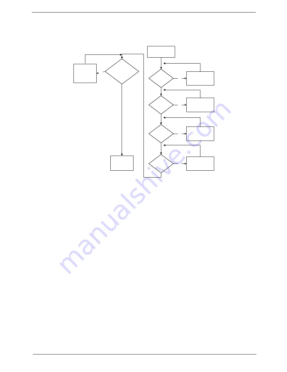
No POST or Video
If the POST or video doesn’t display, perform the following actions one at a time to correct the problem.
1.
Make sure that the internal display is selected. On this notebook model, switching between the internal
display and the external display is done by pressing
Fn+F5
. Reference Product pages for specific model
procedures.
2.
Make sure the computer has power by checking at least one of the following occurs:
•
Fans start up
•
Status LEDs light up
If there is no power, see “Power On Issue” on page 196.
3.
Drain any stored power by removing the power cable and battery and holding down the power button for
10 seconds. Reconnect the power and reboot the computer.
4.
Connect an external monitor to the computer and switch between the internal display and the external
display is by pressing
Fn+F5
(on this model).
If the POST or video appears on the external display, see “LCD Failure” on page 199.
5.
Disconnect power and all external devices including port replicators or docking stations. Remove any
memory cards and CD/DVD discs. Restart the computer.
If the computer boots correctly, add the devices one by one until the failure point is discovered.
6.
Reseat the memory modules.
7.
Remove the drives (see “Disassembly Process” on page 54).
8.
If the Issue is still not resolved, see “Online Support Information” on page 305.
START
Power On?
No
goto no power
trouble shooting
step
Replace
Ext. DDR RAM
module
No
No
Screw it well
Replace
M/B
Connect
it well
No
LCD module
OK?
No
Replace
LCD panel/
LCD cable
Ext. DDRRAM
module well
connected?
Ext. DDRRAM
module OK?
CPU thermal
module well
screw?
Содержание Aspire 8935G
Страница 6: ...VI ...
Страница 44: ...34 Chapter 1 ...
Страница 62: ...52 Chapter 2 ...
Страница 78: ...68 Chapter 3 4 Remove the TV Tuner as shown ...
Страница 80: ...70 Chapter 3 4 Detach the WLAN Module from the WLAN socket ...
Страница 94: ...84 Chapter 3 10 Remove the Upper Cover as shown Upper Cover green callout M2 3 1 Step Size Quantity Screw Type ...
Страница 97: ...Chapter 3 87 5 Lift the board clear of the Upper Cover ...
Страница 100: ...90 Chapter 3 5 Lift the Media Board clear of the Upper Cover ...
Страница 106: ...96 Chapter 3 8 Lift the board clear of the Upper Cover ...
Страница 109: ...Chapter 3 99 5 Remove the Bluetooth Board from the Lower Cover ...
Страница 118: ...108 Chapter 3 4 Using both hands lift the Subwoofer clear of the Lower Cover ...
Страница 155: ...Chapter 3 145 3 Press down around the perimeter of the bezel to secure it in place ...
Страница 165: ...Chapter 3 155 3 Insert the Subwoofer cable into the cable channel Ensure that the cable passes under all cable clips ...
Страница 173: ...Chapter 3 163 4 Connect the Bluetooth cable to the Mainboard ...
Страница 184: ...174 Chapter 3 4 Connect the Volume Control FFC to the Media Board and close the locking latch ...
Страница 195: ...Chapter 3 185 Step Size Quantity Screw Type Switch Cover red callout M2 5 6 5 9 Switch Cover green callout M2 5 4 4 ...
Страница 202: ...192 Chapter 3 2 Tighten the seven captive screws in the Lower Door ...
Страница 204: ...194 Chapter 3 ...
Страница 239: ...Chapter 6 229 ...
Страница 316: ...306 Appendix C ...
Страница 320: ...310 ...


