


40
Chapter 2
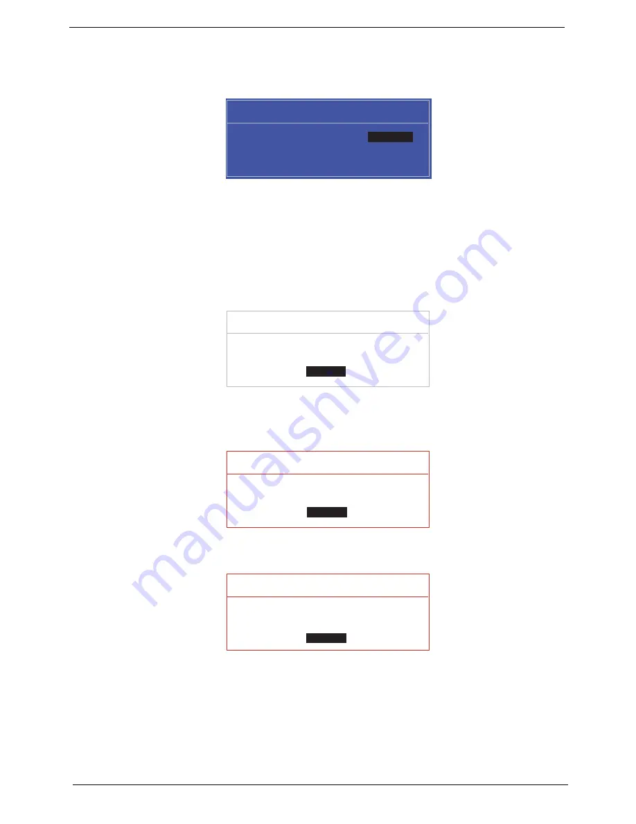
Changing a Password
1.
Use the
↑
and
↓
keys to highlight the Set Supervisor Password parameter and press the
Enter
key. The
Set Password box appears.
2.
Type the current password in the Enter Current Password field and press
Enter
.
3.
Type a password in the Enter New Password field. Retype the password in the Confirm New Password
field.
4.
Press
Enter
. After setting the password, the computer sets the User Password parameter to “Set”.
5.
If desired, you can enable the Password on boot parameter.
6.
When you are done, press F10 to save the changes and exit the BIOS Setup Utility.
If the verification is OK, the screen will display as following.
The password setting is complete after the user presses
Enter
.
If the current password entered does not match the actual current password, the screen will show you the
Setup Warning.
If the new password and confirm new password strings do not match, the screen will display the following
message.
S e t S u p e r v i s o r P a s s w o r d
E n t e r C u r r e n t P a s s w o r d [ ]
[ ]
E n t e r N e w P a s s w o r d [ ]
C o n f i r m N e w P a s s w o r d [ ]
[ ]
S e t u p N o t i c e
C h a n g e s h a v e b e e n s a v e d .
[ C o n t i n u e ]
[
C o n t i n u e
]
S e t u p W a r n i n g
I n v a l i d P a s s w o r d .
[ C o n t i n u e ]
[
C o n t i n u e
]
S e t u p W a r n i n g
P a s s w o r d s d o n o t m a t c h .
R e - e n t e r p a s s w o r d .
[ C o n t i n u e ]
[
C o n t i n u e
]
Содержание Aspire 8935G
Страница 6: ...VI ...
Страница 44: ...34 Chapter 1 ...
Страница 62: ...52 Chapter 2 ...
Страница 78: ...68 Chapter 3 4 Remove the TV Tuner as shown ...
Страница 80: ...70 Chapter 3 4 Detach the WLAN Module from the WLAN socket ...
Страница 94: ...84 Chapter 3 10 Remove the Upper Cover as shown Upper Cover green callout M2 3 1 Step Size Quantity Screw Type ...
Страница 97: ...Chapter 3 87 5 Lift the board clear of the Upper Cover ...
Страница 100: ...90 Chapter 3 5 Lift the Media Board clear of the Upper Cover ...
Страница 106: ...96 Chapter 3 8 Lift the board clear of the Upper Cover ...
Страница 109: ...Chapter 3 99 5 Remove the Bluetooth Board from the Lower Cover ...
Страница 118: ...108 Chapter 3 4 Using both hands lift the Subwoofer clear of the Lower Cover ...
Страница 155: ...Chapter 3 145 3 Press down around the perimeter of the bezel to secure it in place ...
Страница 165: ...Chapter 3 155 3 Insert the Subwoofer cable into the cable channel Ensure that the cable passes under all cable clips ...
Страница 173: ...Chapter 3 163 4 Connect the Bluetooth cable to the Mainboard ...
Страница 184: ...174 Chapter 3 4 Connect the Volume Control FFC to the Media Board and close the locking latch ...
Страница 195: ...Chapter 3 185 Step Size Quantity Screw Type Switch Cover red callout M2 5 6 5 9 Switch Cover green callout M2 5 4 4 ...
Страница 202: ...192 Chapter 3 2 Tighten the seven captive screws in the Lower Door ...
Страница 204: ...194 Chapter 3 ...
Страница 239: ...Chapter 6 229 ...
Страница 316: ...306 Appendix C ...
Страница 320: ...310 ...


