


10
Chapter 1
Indicators
The computer has several easy-to-read status indicators:
The front panel indicators are visible even when the computer cover is closed.
NOTE:
1.
Charging:
The battery light shows amber when the battery is charging. 2.
Fully charged:
The light
shows green when in AC mode.
Easy-Launch Buttons
Located beside the keyboard are application buttons. These buttons are called easy-launch buttons. They are:
WLAN, Internet, email, Bluetooth, Arcade and Acer Empowering Technology.
The mail and Web browser buttons are pre-set to email and Internet programs, but can be reset by users. To
set the Web browser, mail and programmable buttons, run the Acer Launch Manager.
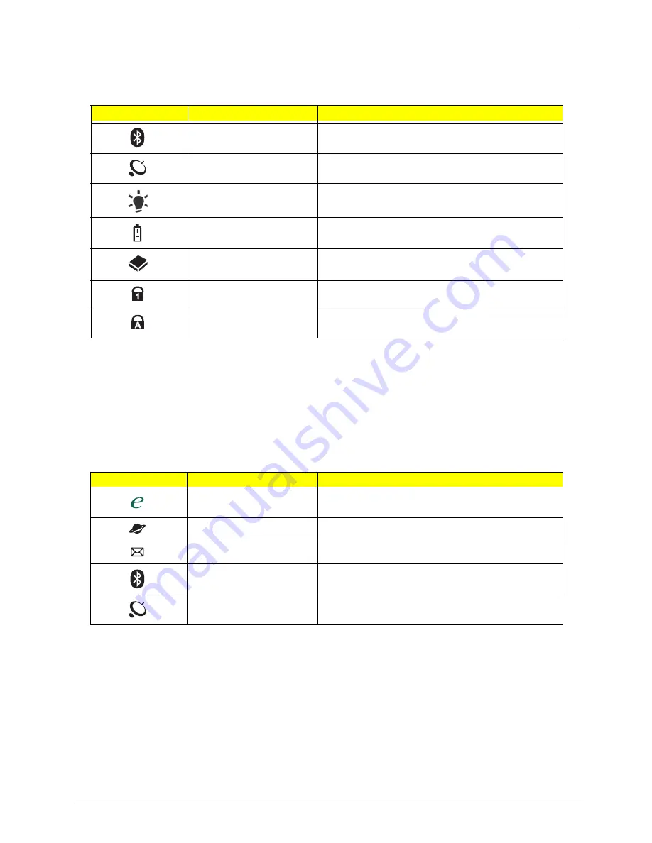
Icon
Function
Description
Bluetooth
Indicates the status of Bluetooth communication.
WLAN
Indicates the status of wireless LAN
communication.
Power
Indicates the computer's power status.
Battery
Indicates the computer's battery status.
HDD
Indicates when the hard disk drive is active.
Num Lock
Lights up when Num Lock is activated.
Caps Lock
Lights up when Caps Lock is activated.
Icon
Function
Description
Empowering Technology
Launch Acer Empowering Technology.
(user-programmable)
Web browser
Internet browser (user-Programmable)
Email application (user-Programmable)
Bluetooth communication
switch
Enables/disables the Bluetooth function.
Wireless communication
switch
Enables/disables the wireless function.
Содержание Aspire 6530 Series
Страница 6: ...VI...
Страница 10: ...X Table of Contents...
Страница 14: ...4 Chapter 1 System Block Diagram...
Страница 49: ...Chapter 2 39 3 Reboot the system and key in the selected string qjjg9vy 07yqmjd etc for the BIOS user password...
Страница 50: ...40 Chapter 2...
Страница 64: ...54 Chapter 3 5 Lift the HDD carrier to remove 6 Grasp the HDD connector and pull firmly to remove...
Страница 85: ...Chapter 3 75 4 Grasp the module by the right side and lift up to remove...
Страница 93: ...Chapter 3 83 7 Disconnect the Mic cable and remove the LCD bezel...
Страница 104: ...94 Chapter 3 4 Replace the ten securing screws and screw caps on the LCD bezel...
Страница 106: ...96 Chapter 3 3 Connect fan cable to the mainboard as shown...
Страница 111: ...Chapter 3 101 2 Reconnect the TouchPad and Finger Print Reader FFCs as shown...
Страница 120: ...110 Chapter 3 7 Turn the computer over and replace the ten screws as shown...
Страница 155: ...Chapter 5 145 Jumper and Connector Locations Top View Chapter 5...
Страница 156: ...146 Chapter 5 Bottom View...
Страница 172: ...162 Chapter 6 Screw List Category Description Acer P N SCREW SCREW SCREW SCREW SCREW SCREW SCREW SCREW SCREW...
Страница 173: ...Chapter 6 163...
Страница 220: ...210 Appendix B...
Страница 222: ...212 Appendix C...


