Chapter 3
63
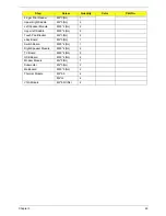
Finger Print Reader
M2*3 (NL)
1
Upper Right Saddle
M2*3 (NL)
2
Left Speaker Module
M2.5*4 (NL)
2
Upper left Saddle
M2.5*4 (NL)
2
Touch Pad Bracket
M2*3 (NL)
2
eKey Board
M2*3 (NL)
1
Switch Board
M2.5*4 (NL)
1
Right Speaker Module
M2.5*4 (NL)
2
TV Board
M2.5*4 (NL)
2
USB Board
M2.5*4 (NL)
2
Modem Module
M2*3 (NL)
1
Subwoofer
M2*3 (NL)
2
Mainboard
M2.5*5 (NL)
2
Thermal Module
M2*6.5
4
M2*L3
4
VGA Module
M2*4-NI (NL)
2
Step
Screw
Quantity
Color
Part No.
Содержание Aspire 5230
Страница 6: ...VI ...
Страница 14: ...4 Chapter 1 System Block Diagram ...
Страница 64: ...52 Chapter 3 6 Remove the HDD cover as shown 7 Remove the WLAN cover as shown ...
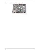
Страница 85: ...Chapter 3 73 6 Turn the upper cover over The upper cover appears as follows ...
Страница 106: ...94 Chapter 3 7 Lift the Thermal Module clear of the Mainboard ...
Страница 112: ...100 Chapter 3 6 Disconnect the left and right Inverter board cables as shown ...
Страница 126: ...114 Chapter 3 3 Replace the RJ 11 cable in its housing ...
Страница 137: ...Chapter 3 125 2 Replace the bracket as shown 3 Replace the single securing screw ...
Страница 140: ...128 Chapter 3 2 Connect the seven cables on the mainboard as shown B C D E F G A ...
Страница 146: ...134 Chapter 3 7 Replace the adhesive strip to secure the cable 8 Replace bracket and secure with provided screw ...
Страница 152: ...140 Chapter 3 ...
Страница 193: ...Chapter 6 181 ...
Страница 200: ...188 Appendix B ...
Страница 202: ...190 Appendix C ...
Страница 205: ...193 Windows 2000 Environment Test 184 Wireless Function Failure 154 WLAN Board 54 ...
Страница 206: ...194 ...


