


24
Chapter 2
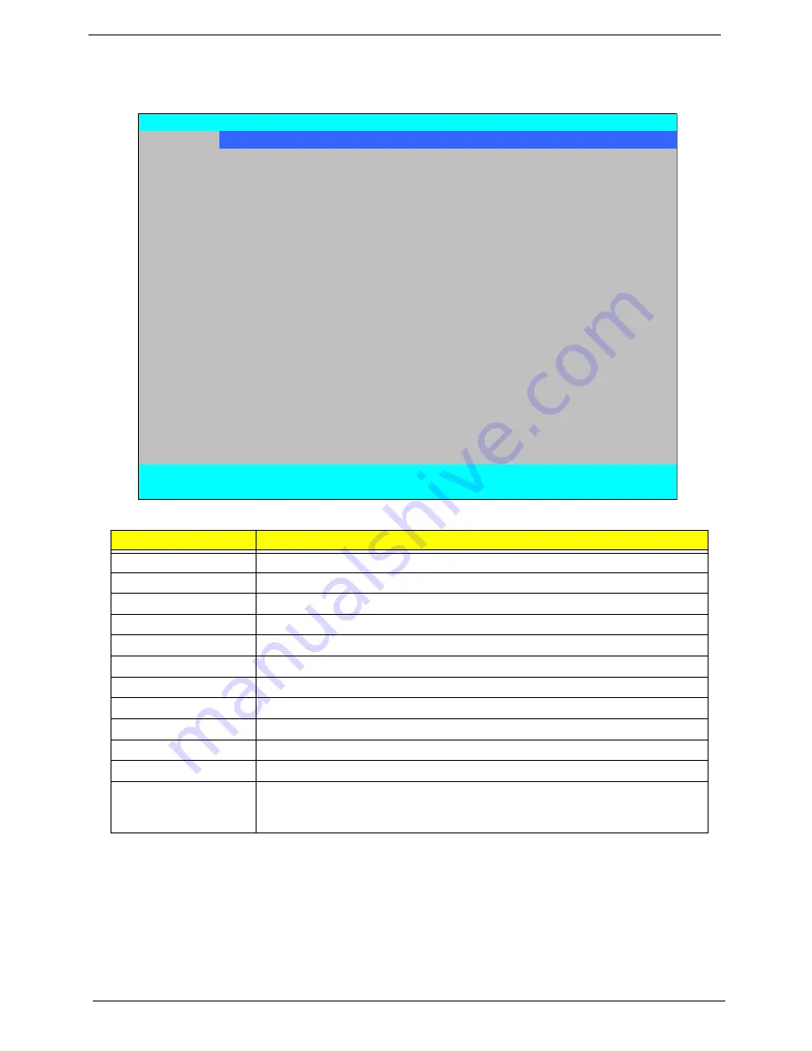
Information
The Information screen displays a summary of your computer hardware information.
NOTE:
The system information is subject to different models.
Parameter
Description
CPU Type
This field shows the CPU type and speed of the system.
CPU Speed
This field shows the speed of the CPU.
HDD Model Name
This field shows the model name of HDD installed on primary IDE master.
HDD Serial Number
This field displays the serial number of HDD installed on primary IDE master.
ATAPI Model Name
This field shows the model name of the Optical device installed in the system.
System BIOS Version
Displays system BIOS version.
VGA BIOS Version
This field displays the VGA firmware version of the system.
Serial Number
This field displays the serial number of this unit.
Asset Tag Number
This field displays the asset tag number of the system.
Product Name
This field shows product name of the system.
Manufacturer Name
This field displays the manufacturer of this system.
UUID Number
Universally Unique Identifier (UUID) is an identifier standard used in software
construction, standardized by the Open Software Foundation (OSF) as part of
the Distributed Computing Environment (DCE).
InsydeH20 Setup Utility
Rev. 3.5
Information
Main Advanced
Security
Power
Boot
Exit
CPU Type:
Intel (R) Core (TM)2 Duo CPU P9500 @ 2.53GHz
CPU Speed:
2.53GHz
HDD Model Name:
WDC WD3200BEVT-22ZCTO
HDD Serial Number:
WD-WXEY07340577
ATAPI Model Name:
Optiarc BD ROM BC-5500S
System BIOS Version:
V0.17-T01
VGA BIOS Version:
Intel V1598
Serial Number:
Asset Tag Number:
Product Name:
Manufacturer Name:
Acer
UUID:
FFFFFFFF-FFFF-FFFF-FFFF-002007011606
F1
Help
↑↓
Select Item
F5/F6
Change Values
F9
Setup Default
ESC
Exit
←→
Select Menu
Enter
Select
X
SubMenu
F10
Save and Exit
Содержание Aspire 2430
Страница 6: ...VI ...
Страница 10: ...X Table of Contents ...
Страница 32: ...22 Chapter 1 ...
Страница 59: ...Chapter 3 49 5 Detach the WLAN board from the WLAN socket ...
Страница 71: ...Chapter 3 61 5 Remove both Speaker Modules ...
Страница 73: ...Chapter 3 63 7 Place the computer rightside up and remove the cables from the housing ...
Страница 83: ...Chapter 3 73 4 Grasp the left side of the bracket and angle upwards to remove ...
Страница 89: ...Chapter 3 79 5 Lift the module from the mainboard ...
Страница 99: ...Chapter 3 89 4 Lift up the bezel and disconnect the MIC module 5 Remove the bezel from the LCD module ...
Страница 101: ...Chapter 3 91 5 Disconnect the left and right Inverter board cables as shown ...
Страница 117: ...Chapter 3 107 6 Replace the three securing screws ...
Страница 131: ...Chapter 3 121 Replacing the DIMM Modules 1 Replace the DIMM modules bottom first and press down to lock in place ...
Страница 134: ...124 Chapter 3 ...
Страница 156: ...146 Chapter 4 ...
Страница 173: ...Chapter 6 163 ...
Страница 238: ...Appendix A 228 ...
Страница 244: ...234 Appendix B ...
Страница 246: ...236 Appendix C ...
Страница 249: ...239 Wireless Function Failure 138 WLAN Board 48 ...
Страница 250: ...240 ...


