


Chapter 1
9
Indicators
The computer has several easy-to-read status indicators. The front panel indicators are visible even when the
computer cover is closed.
NOTE:
1.
Charging:
The light shows amber when the battery is charging. 2.
Fully charged:
The light shows
green when in AC mode.
Easy-Launch Buttons
Located beside the keyboard are application buttons. These buttons are called easy-launch buttons. They are:
WLAN, Internet, email, Bluetooth and Acer Empowering Technology.
The mail and Web browser buttons are pre-set to email and Internet programs, but can be reset by users. To
set the Web browser, mail and programmable buttons, run the Acer Launch Manager, you can access the
Launch Manager by clicking on Start, All Programs, and then Launch Manager to start the application.
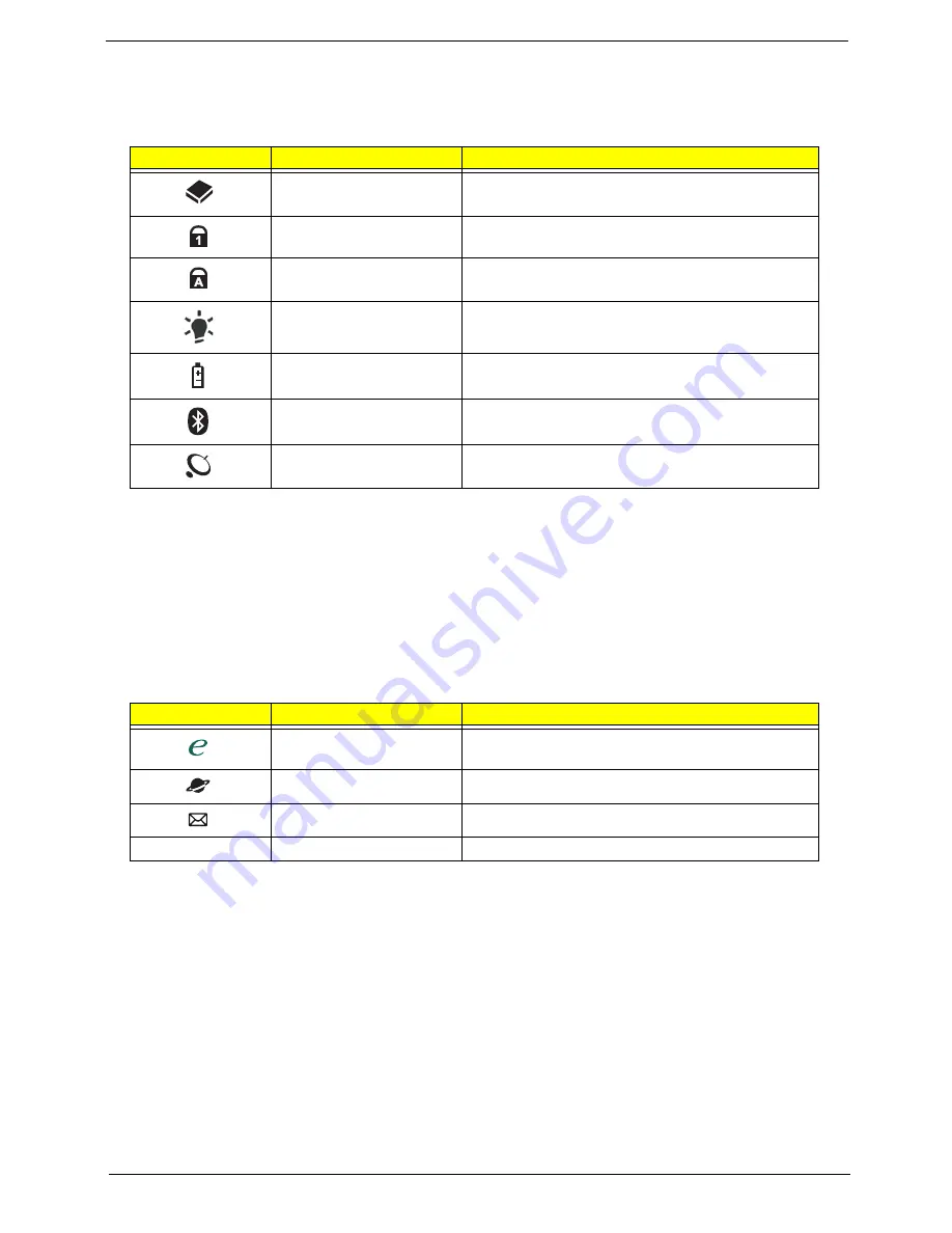
Icon
Function
Description
HDD
Indicates when the hard disk drive is active.
Num Lock
Lights up when Num Lock is activated.
Caps Lock
Lights up when Caps Lock is activated.
Power
Indicates the computer's power status.
Battery
Indicates the computer's battery status.
Bluetooth communication
button/indicator
Enables/disables the Bluetooth function. Indicates
the status of Bluetooth communication.
Wireless communication
button/indicator
Enables/disables the wireless function. Indicates
the status of wireless LAN communication.
Icon
Function
Description
Empowering Technology
Launch Acer Empowering Technology.
(user-programmable)
Web browser
Internet browser (user-Programmable)
Email application (user-Programmable)
P
Programmable key
User-programmable
Содержание Aspire 2430
Страница 6: ...VI ...
Страница 10: ...X Table of Contents ...
Страница 32: ...22 Chapter 1 ...
Страница 59: ...Chapter 3 49 5 Detach the WLAN board from the WLAN socket ...
Страница 71: ...Chapter 3 61 5 Remove both Speaker Modules ...
Страница 73: ...Chapter 3 63 7 Place the computer rightside up and remove the cables from the housing ...
Страница 83: ...Chapter 3 73 4 Grasp the left side of the bracket and angle upwards to remove ...
Страница 89: ...Chapter 3 79 5 Lift the module from the mainboard ...
Страница 99: ...Chapter 3 89 4 Lift up the bezel and disconnect the MIC module 5 Remove the bezel from the LCD module ...
Страница 101: ...Chapter 3 91 5 Disconnect the left and right Inverter board cables as shown ...
Страница 117: ...Chapter 3 107 6 Replace the three securing screws ...
Страница 131: ...Chapter 3 121 Replacing the DIMM Modules 1 Replace the DIMM modules bottom first and press down to lock in place ...
Страница 134: ...124 Chapter 3 ...
Страница 156: ...146 Chapter 4 ...
Страница 173: ...Chapter 6 163 ...
Страница 238: ...Appendix A 228 ...
Страница 244: ...234 Appendix B ...
Страница 246: ...236 Appendix C ...
Страница 249: ...239 Wireless Function Failure 138 WLAN Board 48 ...
Страница 250: ...240 ...


