


126
Chapter 4
Power On Issue
If the system doesn’t power on, perform the following actions one at a time to correct the problem. Do not
replace a non-defective FRUs:
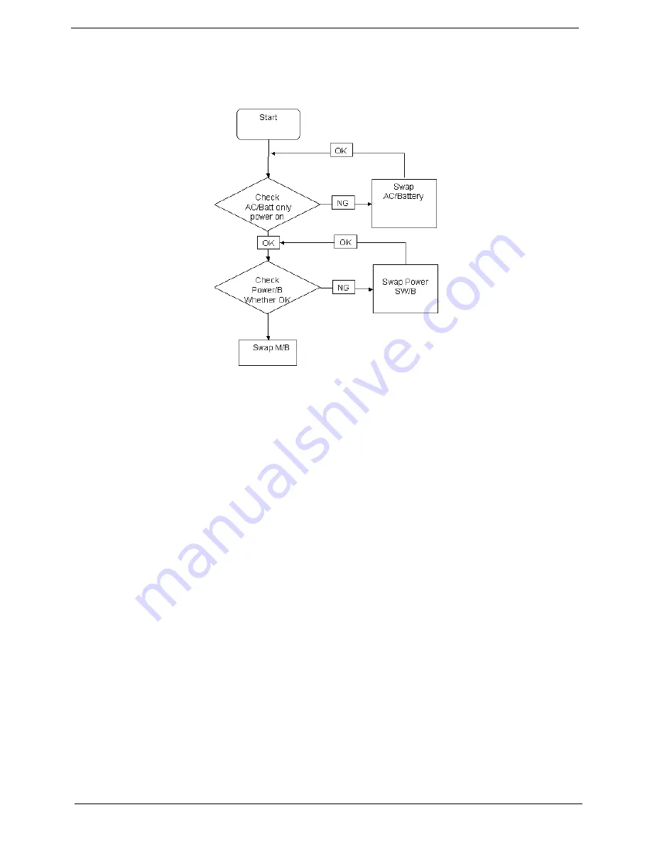
Computer Shutsdown Intermittently
If the system powers off at intervals, perform the following actions one at a time to correct the problem.
1.
Check the power cable is properly connected to the computer and the electrical outlet.
2.
Remove any extension cables between the computer and the outlet.
3.
Remove any surge protectors between the computer and the electrical outlet. Plug the computer directly
into a known good electrical outlet.
4.
Disconnect the power and open the casing to check the Thermal Unit (see “Thermal Unit Failure” on page
140) and fan airways are free of obstructions.
5.
Disable the power management settings in the BIOS to ensure they are not the cause of the problem (see
“Power” on page 31).
6.
Remove all external and non-essential hardware connected to the computer that are not necessary to
boot the computer to the failure point.
7.
Remove any recently installed software.
8.
If the Issue is still not resolved, see “Online Support Information” on page 235.
Содержание Aspire 2430
Страница 6: ...VI ...
Страница 10: ...X Table of Contents ...
Страница 32: ...22 Chapter 1 ...
Страница 59: ...Chapter 3 49 5 Detach the WLAN board from the WLAN socket ...
Страница 71: ...Chapter 3 61 5 Remove both Speaker Modules ...
Страница 73: ...Chapter 3 63 7 Place the computer rightside up and remove the cables from the housing ...
Страница 83: ...Chapter 3 73 4 Grasp the left side of the bracket and angle upwards to remove ...
Страница 89: ...Chapter 3 79 5 Lift the module from the mainboard ...
Страница 99: ...Chapter 3 89 4 Lift up the bezel and disconnect the MIC module 5 Remove the bezel from the LCD module ...
Страница 101: ...Chapter 3 91 5 Disconnect the left and right Inverter board cables as shown ...
Страница 117: ...Chapter 3 107 6 Replace the three securing screws ...
Страница 131: ...Chapter 3 121 Replacing the DIMM Modules 1 Replace the DIMM modules bottom first and press down to lock in place ...
Страница 134: ...124 Chapter 3 ...
Страница 156: ...146 Chapter 4 ...
Страница 173: ...Chapter 6 163 ...
Страница 238: ...Appendix A 228 ...
Страница 244: ...234 Appendix B ...
Страница 246: ...236 Appendix C ...
Страница 249: ...239 Wireless Function Failure 138 WLAN Board 48 ...
Страница 250: ...240 ...


