Chapter 3
35
External Module Disassembly Process
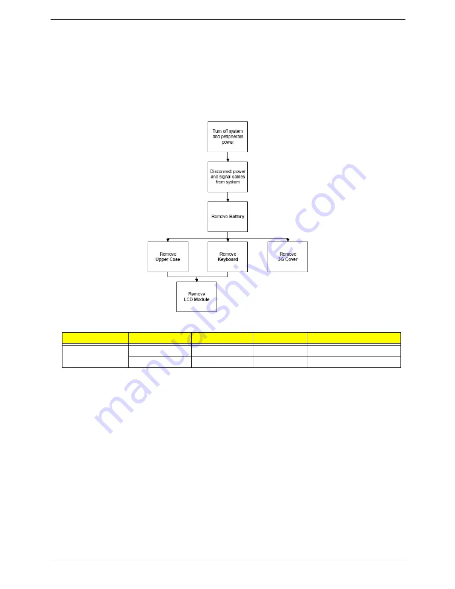
External Modules Disassembly Flowchart
The flowchart below gives you a graphic representation on the entire disassembly sequence and instructs you
on the components that need to be removed during servicing. Disassembly is divided into two tiers. Tier 1
comprises of FRU parts that do not require complete disassembly of the computer. Tier 2 incorporates the
remaining FRU parts that require complete disassembly.
Screw List
Step
Screw
Quantity
Color
Part No.
Upper Cover
M2*5
5
Black
86.TG607.004
M2*3 (NL)
3
Black
86.S0207.001
Содержание AO722
Страница 6: ...VI ...
Страница 10: ...X Table of Contents ...
Страница 13: ...Chapter 1 3 System Block Diagram ...
Страница 28: ...18 Chapter 1 ...
Страница 41: ...Chapter 2 31 3 Reboot the system and key in the selected string qjjg9vy 07yqmjd etc for the BIOS user password ...
Страница 42: ...32 Chapter 2 ...
Страница 72: ...62 Chapter 3 5 Remove the thermal module ...
Страница 79: ...Chapter 3 69 3 Replace the two adhesive strips ...
Страница 88: ...78 Chapter 3 ...
Страница 120: ...110 Chapter 4 ...
Страница 137: ...Chapter 6 127 ...
Страница 172: ...162 Appendix C ...


