


A p p e n d i x G
A p p e n d i x G
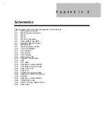
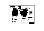
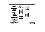
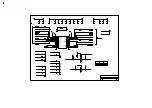
Schematics
This appendix shows the schematic diagrams of the notebook.
G-1
CPU Board Connector
G-2
M1531 Bypass Capacitors
G-3
M1531
G-4
M1533
G-5
M1533 Configuration
G-6
Cache RAM & Tag RAM
G-7
16M EDO DRAM on board
G-8
DIMM Socket
G-9
Clock Generator CY2272
G-10
VGA Chip NM2097
G-11
LCD Interface
G-12
LCD Inverter
G-13
CRT Interface
G-14
HDD, media LED
G-15
CD-ROM, Internal FDD
G-16
USB
G-17
RTC, ROM
G-18
Keyboard Controller M38813
G-19
Fax/.Modem, Golden Finger
G-20
Super I/O 97338
G-21
Serial Port
G-22
Parallel Port, External FDD
G-23
Audio Chip YMF715 OPL3-SA3
G-24
OP-AMP
G-25
PCMCIA Controller OZ6833
G-26
TPS2206 & Socket
G-27
DC/DC, Charger, Battery Board
G-28
Skew Holes
Содержание 365 Series
Страница 80: ...Silk Screen D 2 PCB No 96532 SA CPU Board Layout Bottom ...
Страница 82: ...Mainboard Layout ...
Страница 83: ...Bottom ...
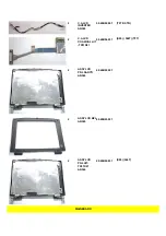
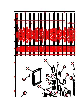
Страница 95: ... S S S H Q G S H Q G L L Explored View Diagram ...
Страница 96: ......
Страница 100: ......
Страница 101: ......
Страница 115: ......
Страница 117: ......
Страница 120: ......
Страница 122: ......
Страница 126: ......


