


Disassembly and Unit Replacement
3-19
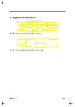
3.6.7
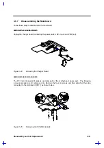
Disassembling the Mainboard
Follow these steps to disassemble the mainboard:
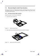
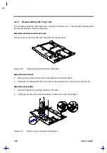
REMOVING THE CHARGER BOARD
Unplug the charger board (containing the power switch, DC-in jack and PS/2 port).
Figure 3-24
Removing the Charger Board
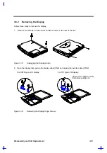
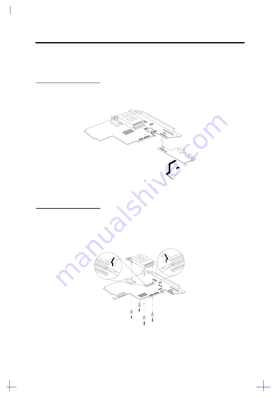
REMOVING THE PCMCIA SOCKETS
The PC Card Connector Module is normally part of the motherboard spare part. The following
removal procedure is for reference only. Remove the four (4) screws and then detached the cable
connected to the mainbaord (CN11) as shown below.
Figure 3-25
Removing the PCMCIA Sockets
Содержание 365 Series
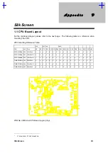
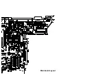
Страница 80: ...Silk Screen D 2 PCB No 96532 SA CPU Board Layout Bottom ...
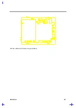
Страница 82: ...Mainboard Layout ...
Страница 83: ...Bottom ...
Страница 95: ... S S S H Q G S H Q G L L Explored View Diagram ...
Страница 96: ......
Страница 100: ......
Страница 101: ......
Страница 115: ......
Страница 117: ......
Страница 120: ......
Страница 122: ......
Страница 126: ......


