INS401 User’s Manual
_____________________________________________________________________________________
Doc# 7430-3305-08
Page 33
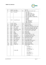
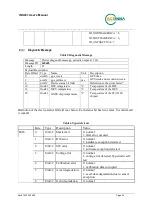
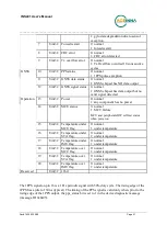
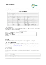
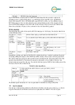
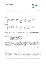
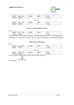
Receive:
Header
Msg_Type Length
Data
CRC
0x5555
0xaa03
0
--
2 bytes
start Addr is the starting address of each frame of data writing, with the high byte first.
EXAMPLE
The starting address of the first frame of data writing is 0, and 192 bytes are written. Then the
starting address of the second frame of data should be 192.
When receiving the first frame of write command, BootLoader will erase the flash first. Please
wait until the erase is complete.
At the same time, ensure that Length = Nu 8, and the written BinData is a multiple of
16, otherwise Msg_Type = 0 will show in the message returned by BootLoader.
When writing is successful, Length = 0 will show in the message returned by BootLoader.
INS401 IMU FW Upgrade
When upgrading the IMU, make sure that INS401 is in APP mode, otherwise the upgrade will
not be possible.
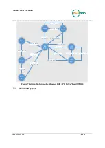
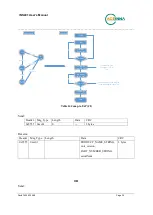
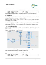
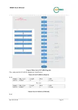
The IMU FW upgrade process is shown in Figure 8.
INS
APP
IMU
APP
IMU Boot Cmd
IMU
Boot
IMU Boot flag True
IMU Write app
IMU Jump to APP
IMU Boot Flag False
State diagram
Recv JI
(Jump 2 IAP)
Is in IAP?
N
Start
IMU APP
Y
Recv WA
(Write IMU APP)
Write Finish?
N
Recv JA
(Jump 2 IMU
APP)
Y
END
flow chart
Start
INS APP
IMU JI
IMU JA
IMU WA
Check Boot Flag
Set Boot Flag
Into APP
Set Boot Flag
Into Boot
Figure 8 State Diagram and Flowchart of INS401 IMU FW Upgrade
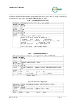
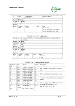
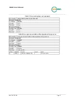
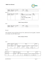
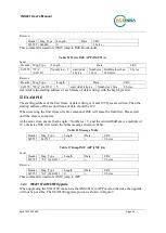
The commands for INS401 IMU FW upgrade are listed below.
Table 20 IMU Jump to IAP (IMU JI)
Send:
Header Msg_Type
Length
Data
CRC
0x5555 0x4a49
0
--
2 bytes

