INS401 User’s Manual
_____________________________________________________________________________________
Doc# 7430-3305-08
Page 9
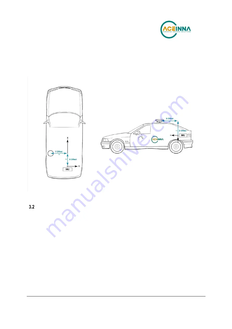
required to have the lever arm accuracy of less than 2 cm. For instance, a lever arm measurement
is shown in Figure 5. The translation offset is measured as 1 m in each direction of x, y, z. The
IMU to the GNSS antenna lever arm is [x, y, z] = [1.0, -1.0, -1.0] m. The “Set User
Configuration” command in Table 11 should be used to configure the INS401 with the correct
lever arm.
Figure 5 INS401 IMU to GNSS Antenna Lever Arm Definition and Measurement Demonstration
Antenna Selection and Connection
The INS401 works with a customized external wiring harness to connect to the antenna
connector and the main connector.
Connect antenna cable to FAKRA-J C type RF terminal
Connect power supply, Ethernet, PPS signal to main connector MX23A18NF1
The INS401 will supply power (+5Vdc) to the antenna via the antenna cable
Based on your application, select an GNSS L1&L2 active antenna. A typical antenna LNA gain
between 30 dB and 45 dB is recommended.
When installing the GNSS antenna:
1)
Choose an antenna location with a clear view of the sky so each satellite above the horizon
can be tracked without obstruction
2)
Mount the antenna on a secure, stable structure capable of safe operation in the specific
environment


