background image

INS401 User’s Manual


_____________________________________________________________________________________ 

Doc# 7430-3305-08 


Page 25 


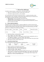
commands and the INS401 response message are defined in pairs, where the request command is 
a two-byte hex value that is also the ID of the response message. 

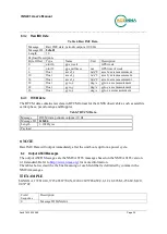
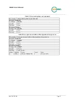
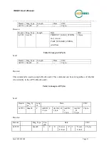
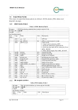
Table 9 Get the Product Information 

Description 

Get the product device information, as per user poll 

Request Command: 

Command 

0xcc01 

Length 

0


Payload 

None 

Response Message:


Message ID

  0xcc01 

Length 

N/A 

Payload 

ASCII message (separated by space), e.g. 
INS401 8550-4006-01 21090xxxxx  Hardware v1.0 

Product

    (P/N)         (S/N)                 (HW Version)  


RTK_INS  Firmware v28.XX.XX  

     Bootloader v01.xx.xx  

     (FW 

Version)                                      (Bootloader Version) 

IMU FW  v27.00.XX        STA9100 FW v5.XX.XX 

 (IMU FW version)       (STA9100 FW version) 


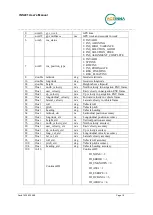
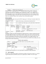
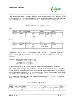
Table 10 Get User Configuration 

Description 

Get user configuration on the parameters (defined in Table 13) 

Request Command: 

Command 

0xcc02 

Length 

Payload 

Sequence ID as defined in Table 13 

Response Message:


Message ID

  0xcc02 

Length 

4 bytes (Sequence ID) + length of parameter value (each defined in Table 
13)


content 


offset 

variable 

name 

unit 

desc 

uint32 

Sequence ID 


refer to Table 13 


parameter value 


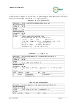
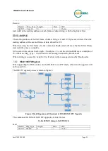
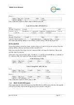
Table 11 Set User Configuration 

Description 

Set user configuration on the parameters (defined in Table 13)  

Request Command: 

Command 

0xcc03 

Length 

4 bytes (Sequence ID) + length of parameter value


Payload 


offset 

variable 

name 

unit 

desc 

Содержание INS401

Страница 1: ...ACEINNA Inc email info aceinna com website www aceinna com INS401 USER MANUAL Preliminary Document Part Number 7430 4006 02 ...

Страница 2: ...nce with any military specifications or that the product is appropriate for any military application or end use Additionally any use of this product for nuclear chemical biological weapons or weapons research or for any use in missiles rockets and or UAV s of 300km or greater range or any other activity prohibited by the Export Administration Regulations is expressly prohibited without the written...

Страница 3: ...nna Selection and Connection 9 Power Requirement 10 INS401 Operation 11 Setting Up Communications 11 System Operation and Data Logging 11 RTK Corrections 14 Odometer 14 Diagnostic Capabilities 16 Ethernet Port and Messages 17 Ethernet Data Frame Definition 17 Aceinna Binary Packet Format 17 Output Binary Packets 18 GNSS Solution Packet 18 INS navigation solution 18 Diagnostic Message 20 Raw IMU Da...

Страница 4: ...0 3305 08 Page 2 INS401 APP Upgrade 29 INS401 IMU FW Upgrade 33 INS401 STA9100 FW Upgrade 34 Appendix A 16 bit CRC Implementation Sample Code 37 Appendix B AceNav CLI Software Usage 38 System requirement 38 GNSS INS operation user settings 38 Commands 38 Appendix C Firmware 28 01 and Earlier IMU Axis Definition 40 ...

Страница 5: ...he topic EXAMPLE Examples are given throughout the manual to help the reader understand the terminology IMPORTANT This symbol defines items that have significant meaning to the user WARNING The user should pay particular attention to this symbol It means there is a chance that physical harm could happen to either the person or the equipment The following paragraph heading formatting is used in thi...

Страница 6: ...for easy evaluation and flexible deployment for various applications including automotive applications and ADAS systems The Aceinna INS401 supports multiple constellations GPS GLONASS Galileo Beidou and QZSS It tracks the following satellite signals shown in Table 1 Table 1 INS401 Frequency Plan Constellation Satellite Signals GPS L1 C A L2C GLONASS G1 BeiDou B1I B2I Galileo E1 E5b QZSS L1C A L2C ...

Страница 7: ...t range and is designed and qualified to withstand the worst case conditions in terms of overvoltage reverse voltage and other fault conditions experienced in these vehicles Housing and Dimensions The INS401 housing is cast aluminum for ruggedness and low manufacturing cost as shown in Figure 1 There are two connectors on the front panel and they are permanently installed into the INS401 housing T...

Страница 8: ...s Mechanical Interface RF Connector An automotive grade FAKRA J C type connector manufactured by Molex is used for the GNSS antenna connection Its manufacturing part number is 734035112 The mating connector has part number 734036262 The center conductor carries the RF signal into the INS401 receiver and delivers 5 V DC from the INS401 to the external active antenna ...

Страница 9: ...onnector from outside the module Figure 3 Pin Diagram of the Male End Table 2 shows the functional description of the 18 pins in the main connector Table 2 Pin Description of the Main Connector Pin Number Type Pin Name Pin Function 1 Reserved N A Reserved 2 Reserved N A Reserved 3 I O ETH_TRX_N Ethernet negative 4 I O ETH_TRX_P Ethernet positive 5 Reserved N A Reserved 6 Reserved N A Reserved 7 Re...

Страница 10: ...re versions 28 01 and earlier the default IMU body frame orientation was different with the X axis pointing to the same direction as the connectors Z axis pointing down and Y axis completing a right hand coordinate system To align with the vehicle frame definition the INS401 should be mounted on the vehicle with the connectors facing the tail of the vehicle i e the X axis of the IMU body frame poi...

Страница 11: ...rement Demonstration Antenna Selection and Connection The INS401 works with a customized external wiring harness to connect to the antenna connector and the main connector Connect antenna cable to FAKRA J C type RF terminal Connect power supply Ethernet PPS signal to main connector MX23A18NF1 The INS401 will supply power 5Vdc to the antenna via the antenna cable Based on your application select an...

Страница 12: ...___ Doc 7430 3305 08 Page 10 3 Ensure antenna is mounted to a rigid surface to minimize any movement due to vehicle dynamics Power Requirement Operating voltage 12V DC Current requirement The INS401 consumes 4 W typical value It s recommended to make sure the supply is capable of at least 600mA from 12V ...

Страница 13: ...ary data port is the automotive grade ethernet port to connect to a vehicle ECU directly or to a testing computer via a converter The connection to a vehicle ECU is described in the next subchapter for system integration Figure 6 shows a test setup only with a testing PC which requires a key unit and the 100Base TX with RJ 45 connector to 100Base T1 converter to connect an automotive grade etherne...

Страница 14: ...onnect with GNSS antenna 2 Connect the main connector with a MX23A female connector associate cables to the pins defined in Table 2 3 Use an ethernet converter to connect with a testing PC via the RJ 45 jack 4 Power on the system 5 Go to the AceNav CLI folder modify the ins401 json JSON file inside the settings INS401 subfolder input the correct NTRIP account information as shown below 6 Input the...

Страница 15: ...r for the GNSS RTK operation 8 Check the output bin files Every session the AceNav CLI has started a data log subfolder with the time tag in the folder name is created under acenav data The data log subfolder for each data logging session contains four files configuration json INS401 configuration file read from the device flash rtcm_base_ time_tag bin GNSS RTK correction data in RTCM format rtcm_...

Страница 16: ...o Appendix B AceNav CLI Software Usage for a detailed description and the usage of the AceNav CLI RTK Corrections As stated in the overview for optimal performance it is necessary to enable RTK corrections The performance is related to the distance between the rover and the base station ideally 20 km or less The error increases according to the factor of 1 ppm times the baseline length Refer to ch...

Страница 17: ...autocorrelation Normalized error autocorrelation at 1 s below 0 70 mean removed before autocorrelation Error probability density function must be symmetrical small deviations accepted Maximum delay of 0 1 s The vehicular speed must report 0 m s when the vehicle is not moving The vehicular speed must not report 0 m s when the vehicle is moving The vehicular speed must be valid for the entire range ...

Страница 18: ...nual _____________________________________________________________________________________ Doc 7430 3305 08 Page 16 Diagnostic Capabilities Future section Please refer to Table 5 for details on the diagnostic messages ...

Страница 19: ... two packets messages in the same one data frame If one packet message is more than 1500 bytes it is split into two continuous data frames Destination Address Source Address Length User Data Data Frame Checksum 6 bytes 6 bytes 2 bytes 46 to 1500 bytes 4 bytes Destination Address destination MAC address Source Address source MAC address Length length of user data 0 1500 MSB for output message from ...

Страница 20: ...e latitude deg Geodetic latitude 15 double longitude deg Geodetic longitude 23 double height m Height above ellipsoid 31 float latitude_std m Latitudinal position accuracy 35 float longitude_std m Longitudinal position accuracy 39 float height_std m Vertical position accuracy 43 uint8 numberOfSVs Number of satellites 44 uint8 numberOfSVs_in_solution Number of satellites in solution 45 float hdop H...

Страница 21: ...in navigation ENU frame 44 float longitudinal_velocity m s Forward velocity in vehicle frame 48 float lateral_velocity m s Lateral velocity in vehicle frame 52 float roll deg Vehicle roll 56 float pitch deg Vehicle pitch 60 float heading deg Vehicle heading 64 float latitude_std m Latitudinal position accuracy 68 float longitude_std m Longitudinal position accuracy 72 float height_std m Vertical p...

Страница 22: ... o C Temperature of the IMU 14 float32 MCU temperature o C Temperature of the MCU 18 float32 GNSS chip temperature o C Temperature of the STA9100 chipset Definition of the device status bit field is as below Each status bit has two states 0 is valid and 1 is invalid Table 6 Typedef struct Byte Type Description Value IMU 0 Uint32 Master fail 0 normal 1 fatal error occured 1 Uint32 HW error 0 normal...

Страница 23: ...nent has no power 14 Uint32 MCU status 0 normal 1 MCU failure MCU and peripherals HW self test status when power on 15 Uint32 Temperature under MCU flag 0 normal 1 under temperature 16 Uint32 Temperature under STA flag 0 normal 1 under temperature 17 Uint32 Temperature under IMU flag 0 normal 1 under temperature 18 Uint32 Temperature over MCU flag 0 normal 1 under temperature 19 Uint32 Temperature...

Страница 24: ...urement 26 float gyro_z deg s gyro z axis measurement RTCM Data The RTCM data contains raw data in RTCM format for the GNSS observables such as satellite carrier phase pseudo range and Doppler Table 7 RTCM Data Message RTCM data periodic output at 10 Hz Message ID 0x0a06 Length 1 1024bytes Payload NOTE Raw IMU Data will output immediately after the unit boots up from a power cycle Output ASCII Mes...

Страница 25: ...nge 0000 4095 A null field when no reference station ID is available and no corrections are received 15 The checksum data always begins with EXAMPLE GPZDA 172809 40 12 07 1996 00 00 45 Field Sequence Description 0 Message ID GPZDA 1 UTC 2 Day ranging between 01 and 31 3 Month ranging between 01 and 12 4 Year 5 Local time zone offset from GMT ranging from 00 through 13 hours 6 Local time zone offse...

Страница 26: ... Message ID 2 bytes 0x0b02 Length 4 bytes 1024 Payload 1024 bytes base RTCM data 1077 1087 1019 Checksum 2 bytes crc16 check sum Checksum bytes 4 bytes Data frame checksum In addition another user input of the INS401 is defined as below in order to enhance the dead reckoning DR performance of the IMU based INS solution The accurate vehicle speed from the vehicle reference point provides accurate s...

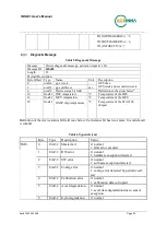
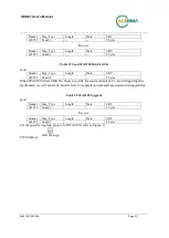
Страница 27: ... S N HW Version RTK_INS Firmware v28 XX XX Bootloader v01 xx xx FW Version Bootloader Version IMU FW v27 00 XX STA9100 FW v5 XX XX IMU FW version STA9100 FW version Table 10 Get User Configuration Description Get user configuration on the parameters defined in Table 13 Request Command Command 0xcc02 Length 4 Payload Sequence ID as defined in Table 13 Response Message Message ID 0xcc02 Length 4 byt...

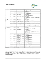
Страница 28: ...age Message ID 0xcc04 Length 4 bytes Payload offset variable name unit desc 0 int32 result 0 success 1 fail Table 13 User Configuration Parameters Sequence ID Type Name Unit Description 1 float gnssLeverArmBx m IMU to GNSS antenna phase center lever arm 2 float gnssLeverArmBy m 3 float gnssLeverArmBz m 4 float vrpLeverArmBx m IMU to vehicle reference point lever arm 5 float vrpLeverArmBy m 6 float...

Страница 29: ...nd 0xcc06 Length N A Payload None Response Message Message ID 0xcc06 Length N A Payload None Table 16 User gets ins save buffer of fixed position of ins power on Description User gets ins save buffer of fixed position of ins power on Request Command Command 0x0a09 Length N A Payload None Response Message Message ID 0x0a09 Length 4 bytes Payload Ins save buffer offset variable name unit desc 0 uint...
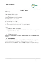
Страница 30: ... burning mode JG Application software returns to GNSS mode from SDK burning mode Notice 1 INS401 only supports Eth port upgrade 2 INS401 only supports the upgrade of APP ST9100 and IMU and does not support the online upgrade of BootLoader FW Upgrade with AceNav Refer to Appendix B AceNav CLI Software Usage for AceNav operation to upgrade INS401 firmware BootLoader Design BootLoader communication f...

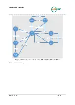
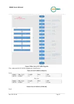
Страница 31: ... Boot Flag True Write APP Write Cmd Jump 2 APP Boot flag False Jump 2 IAP Boot flag True IMU APP IMU Boot Cmd IMU Boot IMU Boot flag True IMU Write app IMU Jump to APP IMU Boot Flag False st9100 Jump to Sdk St9100 Boot St9100 update data Boot flag true Jump to GNSS Boot flag false Figure 7 Relationship between BootLoader IMU APP INS APP and ST9100 INS401 APP Upgrade ...

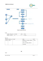
Страница 32: ...rm PC Jump 2 IAP Is in IAP N Start APP CS from PC Set Write Core Y WA from PC Write APP Write Finish N JA from PC Jump to APP Y END Check Write Core Should be C0 or C1 Check Write Num and Msg Len Should be MsgLen Num 8 State diagram flow chart Table 14 Jump to IAP JI Send Header Msg_Type Length Data CRC 0x5555 0xcc01 0 2 bytes Receive Header Msg_Type Length Data CRC 0x5555 0xcc01 PRODUCT_NAME_STRI...

Страница 33: ...serialNum 2 bytes Table 15 Jump to IAP JI Send Header Msg_Type Length Data CRC 0x5555 0xaa01 0 2 bytes Receive This command is used to jump to BootLoader This command can be sent regardless of whether it is currently in the APP or BootLoader Table 16 Jump to APP JA Send Header Msg_Ty pe Leng th Data CRC 0x5555 0xaa02 4 rtkCRC_L 1 byte rtkCRC_H 1 byte insCRC_ L 1 byte insCRC _H 1 byte 2 bytes Recei...

Страница 34: ... C1 corresponds to ins_app Bin size is the length of the actual rtk or ins bin file This value should be sent with the high order first bin_size ptrUcbPacket payload 2 24 ptrUcbPacket payload 3 16 ptrUcbPacket payload 4 8 ptrUcbPacket payload 5 It should be noted that when the host computer reads All bin it confirms the burned bin For example when burning rtk bin in addition to identifying the rtk...

Страница 35: ...wise Msg_Type 0 will show in the message returned by BootLoader When writing is successful Length 0 will show in the message returned by BootLoader INS401 IMU FW Upgrade When upgrading the IMU make sure that INS401 is in APP mode otherwise the upgrade will not be possible The IMU FW upgrade process is shown in Figure 8 INS APP IMU APP IMU Boot Cmd IMU Boot IMU Boot flag True IMU Write app IMU Jump...

Страница 36: ...t frame of data writing is 0 and 192 bytes are written Then the starting address of the second frame of data should be 192 When receiving the first frame of write command IMU will erase the flash first Please wait until the erase is complete At the same time ensure that Length Numbytes 5 and the written BinData is a multiple of 16 otherwise IMU will return the NAK message shown in Table Table 22 M...

Страница 37: ...tep 3 Send boot part1 boot 前5120个字节 Step 4 Send boot part2 boot 剩余字节 Step 5 Return 0xcc Send write flash cmd Send 0x4A Return 0xcc Send app bin info Send bin info 详 细内容参见app信息 Return 0xcc Wait device init Return 0xcc Erase flash Return 0xcc Write app Send bin data 5120bytes each frame thelast frameof data is sent according to the actual length Return 0xcc Check flash crc Return 0xcc End Notice Suc...

Страница 38: ...t 5K Send Header Msg_Type Length Data CRC 0x5555 0xaa08 2 bytes When STA9100 writes SDK bin there is a write timeout mechanism To avoid triggering this mechanism we will send a 5k bin file first So separated commands are used to distinguish this Table 20 STA9100 Upgrade Send Header Msg_Type Length Data CRC 0x5555 0xaa07 2 bytes Receive Header Msg_Type Length Data CRC 0x5555 0xaa07 2 bytes For the ...

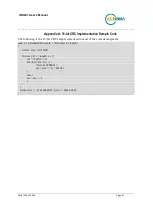
Страница 39: ...7 Appendix A 16 bit CRC Implementation Sample Code The following is the 16 bit CRC sample code used in most of the code development uint16_t CalculateCRC uint8_t buf uint16_t length uint16_t crc 0x1D0F for int i 0 i length i crc buf i 8 for int j 0 j 8 j if crc 0x8000 crc crc 1 0x1021 else crc crc 1 return crc 8 0xFF00 crc 8 0xFF ...

Страница 40: ...N format of configuration file all the user settings including GNSS RTK correction NTRIP account information IMU to GNSS antenna lever arm and so on User must modify the related configurations settings to achieve effective GNSS INS operation For example user should change the NTRIP settings IP address port mount point account and password to accessible GNSS correction service Commands Run the foll...

Страница 41: ...05 08 Page 39 INS401 supports In Application Programming IAP firmware upgrade through the Ethernet interface Run the executable with the CLI option to prompt for user input as below acenav i 100base t1 cli upgrade INS401 FW file path After successful FW upgrade the INS401 system will restart and log data automatically ...

Страница 42: ...__________________________________________________________________________________ Doc 7430 3305 08 Page 40 Appendix C Firmware 28 01 and Earlier IMU Axis Definition Figure 10 IMU Axis Definition and Navigation Center Location ...

Отзывы: