background image

PCI-ICM422/2(4) and 485/2(4) Manual

Page 1-2

Manual MPCI-ICM4S.F1b

A crystal oscillator is located on the card.  This oscillator permits precise selection of baud rates up
to 115,200 or, by changing a jumper, up to 460,800 with the standard crystal oscillator. 

The driver/receiver used, the SN75176B, is capable of driving extremely long communication lines
at high baud rates.  It can drive up to ±60 mA on balanced lines and receive inputs as low as a 200
mV differential signal superimposed on common mode noise of +12 V or -7 V.  In case of
communication conflict, the driver/receivers feature thermal shutdown.

Communication Mode

PCI-ICM422/2 and PCI-ICM422/4  support Full-Duplex and Half-Duplex communications with a
4-wire cable connection. PCI-ICM485/2 and PCI-ICM485/4 support Half-Duplex communications
with a 2-wire cable connection.  Half-Duplex allows traffic to travel in both directions, but only one
way at a time. RS485 communications commonly use the Half-Duplex mode since they share only
a single pair of wires and installation cost is reduced.

Baud Rate Ranges

The card has capability for two  baud rate ranges, selectable on a port-by-port basis.  One range is
for up to 115,200-baud applications and the other is for up to 460,800-baud applications. Refer to
Baud Rate Divisor Table on page 5-2 of the manual.

Auto-RTS Transceiver Control

In RS485 communications, the driver must be enabled and disabled as needed, allowing all cards to
share a 2-wire cable.  The PCI-ICM485/2 and PCI-ICM485/4 cards control the  individual drivers
automatically.  With automatic control, the driver is enabled when data are ready to be transmitted.
The driver remains enabled after data transmission is complete for one additional character's
transmission time and then is disabled.  The receiver is also normally enabled, then disabled during
RS485 transmissions, and then re-enabled after transmission is completed (plus that one character
transmission time).  These cards automatically adjust their timing to the baud rate of the data.  (The
automatic control feature makes the cards ideal for WIN95 applications)

Input/Output Connections

These cards use a 37-pin DBM connector and a breakout cable.  The breakout cable terminates in
a DB9 connector for each port.  Those DB9 connectors are equipped with 4-40 threaded standoffs
(female screw lock) to provide strain relief.  The mating connector is AMP type 17D-E9s or
equivalent.  We recommend using vinyl-jacketed, multiple, twisted-pair cable.

Содержание PCI-ICM422/2

Страница 1: ...ACCES I O PRODUCTS INC 10623 Roselle Street San Diego CA 92121 TEL 858 550 9559 FAX 858 550 7322 MODEL PCI ICM422 485 2 4 USER MANUAL FILE MPCI ICM4S F1b...

Страница 2: ......

Страница 3: ...his document may contain or reference information and products protected by copyrights or patents and does not convey any license under the patent rights of ACCES nor the rights of others IBM PC PC XT...

Страница 4: ...not excluded by warranty Warranty commences with equipment shipment Following Years Throughout your equipment s lifetime ACCES stands ready to provideon site or in plant service at reasonable rates si...

Страница 5: ...apter 2 Installation 2 1 CD Installation 2 1 3 5 Inch Diskette Installation 2 1 Directories Created on the Hard Disk 2 2 Installing the Card 2 4 Input Output Connections 2 5 Chapter 3 Option Selection...

Страница 6: ...d Termination Schematic Page 3 1 Figure 3 2 Option Selection Map Page 3 3 Figure A 1 Typical RS485 Two Wire Multidrop Network Page A 3 List of Tables Table 5 1 Baud Rate Divisor Values Page 5 2 Table...

Страница 7: ...and support termination by jumpers on the card If your application requires the transmitter to be un biased please contact the factory RS485 Balanced Mode Operation The PCI ICM485 2 and PCI ICM485 4 s...

Страница 8: ...port by port basis One range is for up to 115 200 baud applications and the other is for up to 460 800 baud applications Refer to Baud Rate Divisor Table on page 5 2 of the manual Auto RTS Transceive...

Страница 9: ...hat terminateswith female D sub 9 pin connectors Character length 5 6 7 or 8 bits Parity Even odd or none Stop Interval 1 1 5 or 2 bits Serial Data Rates Up to 115 200 baud asynchronous A faster range...

Страница 10: ...PCI ICM422 2 4 and 485 2 4 Manual Page 1 4 Manual MPCI ICM4S F1b Figure 1 1 PCI ICM422 2 4 Block Diagram Only one serial channel shown Figure 1 2 PCI ICM485 2 4 Block Diagram...

Страница 11: ...ompts to install the software for this card WIN95 98 NT 2000 a Place the CD into your CD ROM drive b The CD should automatically runthe install programafter 30 seconds If the install program does not...

Страница 12: ...of CARDNAME that contains C samples Win32 language Subdirectories containing samples for Win95 98 and NT WinRISC exe A Windows dumb terminal type communication program designed for RS422 485 operatio...

Страница 13: ...n programs in DOS PCIFind exe A utility for DOS and Windows to determine what base addresses and IRQs are allocated to installed PCI cards This program runs two versions depending on the operating sys...

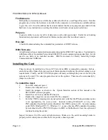
Страница 14: ...e installed in a five volt PCI slot of an IBM or compatible computer Before carefully read the Option Selection section of this manual and configure the card according to your requirements Finally our...

Страница 15: ...ee foot long breakout cable is included with the cards Thatbreakout cable terminates in separate 9 pinDBM connectors oneDB9 per port If desired the cards can be purchased without this breakout cable I...

Страница 16: ...PCI ICM422 2 4 and 485 2 4 Manual Page 2 6 Manual MPCI ICM4S F1b...

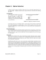
Страница 17: ...elect baud rates in either of two ranges When in the X1 position the baud rate range is up to 115 200 baud When in the X4 position the baud rate range is 200 to 460 800 baud Refer to the Baud Rate Div...

Страница 18: ...vices REG_SZ COM5 InterruptStatus REG_DWORD 0xFC08 InterruptStatus REG_DWORD 0xFC08 PortIndex REG_DWORD 1 PortIndex REG_DWORD 3 Indexed 0 Indexed 0 Serial3 subkey Serial5 subkey PortAddress REG_DWORD...

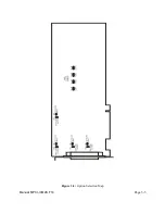
Страница 19: ...Page 3 3 Manual MPCI ICM4S F1b Figure 3 2 Option Selection Map...

Страница 20: ...PCI ICM422 2 4 and 485 2 4 Manual Page 3 4 Manual MPCI ICM4S F1b...

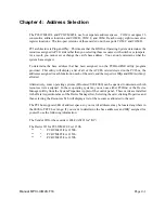
Страница 21: ...etected on the PCI bus the addresses assigned toeach function on each of the cards and the respective IRQs and DMAs if any allotted Alternatively some operating systems Windows95 98 2000 can be querie...

Страница 22: ...PCI ICM422 2 4 and 485 2 4 Manual Page 4 2 Manual MPCI ICM4S F1b...

Страница 23: ...izing the chip requires knowledge of the UART s register set The first step is to set the baud rate divisor You do this by first setting the DLAB Divisor Latch Access Bit high This bit is Bit 7 at Bas...

Страница 24: ...mper Baud Rate Divisor x1 Divisor x4 Notes Max Diff Cable Length 460800 N A 1 230400 N A 2 153600 N A 3 115200 1 4 375 feet 57600 2 8 660 ft 38400 3 12 920 ft 28800 4 16 1165 ft 19200 6 24 1620 ft 144...

Страница 25: ...u do this with two reads from the receiver buffer at base address 0 When done the UART is ready to use Reception Reception can be handled in two ways polling or interrupt driven When polling reception...

Страница 26: ...ASEADDR 2 if readback 4 Readback will be set to 4 if data are available data i inportb BASEADDR outportb 0x20 0x20 Write EOI to 8259 Interrupt Controller return Transmission RS485 transmission is simp...

Страница 27: ...and Rx 3 Tx Tx and Rx 4 5 Ground Ground 6 7 8 9 Rx Table 6 1 Connector Pin Assignments The cards can be ordered without the breakout cable In that case your communication cables will connect directly...

Страница 28: ...PCI ICM422 2 4 and 485 2 4 Manual Page 6 2 Manual MPCI ICM4S F1b...

Страница 29: ...ble This is also true for RS422 but RS485 offers all the benefits of RS422 plus allows up to 32 devices to share the same twisted pairs An exception to the foregoing is that multiple RS422 devices can...

Страница 30: ...x Driver Output Voltage unloaded 4V 6V 4V 6V Driver Output Voltage loaded LD and LDGND 2V jumpers in 2V Driver Output Resistance 50S Driver Output Short Circuit Current 150 mA Driver Output Rise Time...

Страница 31: ...e following illustration shows a typical multidrop or party line network Note that the transmission line is terminated on both ends of the line but not at drop points in the middle of the line Figure...

Страница 32: ...PCI ICM422 2 4 and 485 2 4 Manual Page A 4 Manual MPCI ICM4S F1b...

Страница 33: ...accesioproducts com Customer Comments If you experience anyproblems with this manual or just want to give us some feedback pleaseemail us at manuals accesioproducts com Please detail any errors you fi...

Отзывы: