PCI-ICM422/2(4) and 485/2(4) Manual
Page A-2
Manual MPCI-ICM4S.F1b
A balanced differential line receiver senses the voltage state of the transmission line across the two
signal input lines. If the differential input voltage is greater than +200 mV, the receiver will provide
a specific logic state on its output. If the differential voltage input is less than -200 mV, the receiver
will provide the opposite logic state on its output. A maximum operating voltage range is from +6V
to -6V allows for voltage attenuation that can occur on long transmission cables.
A maximum common mode voltage rating of ±7V provides good noise immunity from voltages
induced on the twisted pair lines. The signal ground line connection is necessary in order to keep
the common mode voltage within that range. The circuit may operate without the ground connection
but may not be reliable.
Parameter
Conditions
M in.
M ax.
Driver Output Voltage (unloaded)
4V
6V
-4V
-6V
Driver Output Voltage (loaded)
LD and LDGND
2V
jump ers in
-2V
Driver Output Resistance
50
S
Driver Output Short-Circuit Current
±150 mA
Driver Output Rise Time
10% unit interval
Rec eiver S ensitivity
±200 mV
Receiver Comm on M ode V oltage Range
±7V
Receiver Input Resistance
4K
S
Table A-2:
RS422 Specification Summary
To prevent signal reflections in the cable and to improve noise rejection in both the RS422 and
RS485 mode, the receiver end of the cable should be terminated with a resistance equal to the
characteristic impedance of the cable. (An exception to this is the case where the line is driven by
an RS422 driver that is never "tristated" or disconnected from the line. In this case, the driver
provides a low internal impedance that terminates the line at that end.)
Note
You do not have to add a terminator resistor to your cables when you use the PCI-ICOM cards.
Termination resistors for the RX+ and RX- lines are provided on the card and are placed in the
circuit when you install the jumpers. (See the Option Selection section of this manual.)
Содержание PCI-ICM422/2
Страница 2: ......
Страница 16: ...PCI ICM422 2 4 and 485 2 4 Manual Page 2 6 Manual MPCI ICM4S F1b...
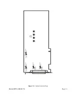
Страница 19: ...Page 3 3 Manual MPCI ICM4S F1b Figure 3 2 Option Selection Map...
Страница 20: ...PCI ICM422 2 4 and 485 2 4 Manual Page 3 4 Manual MPCI ICM4S F1b...
Страница 22: ...PCI ICM422 2 4 and 485 2 4 Manual Page 4 2 Manual MPCI ICM4S F1b...
Страница 28: ...PCI ICM422 2 4 and 485 2 4 Manual Page 6 2 Manual MPCI ICM4S F1b...
Страница 32: ...PCI ICM422 2 4 and 485 2 4 Manual Page A 4 Manual MPCI ICM4S F1b...


