manualshive.com logo in svg
background image

3

25-1, 25-1H

WARNINGS - 

safe use instructions

1.  

Study, understand and follow all instructions before

operating this jack.

2.  

Do not exceed rated capacity.

3.  

Use only on hard level surface.

4.  

It is recommended to brake and chock the vehicle.

5.  

Lifting device only. Immediately after lifting, support

the vehicle with support stands.

6.  

Lift only on areas of the vehicle as specified by the

vehicle manufacturer, and only centrally on the lifting

saddle.

7.  

No person should remain in, on, or get bodily under

a load that is being jacked or is supported only by a

jack.

8.  

Do not use more than 2 standard extensions in

sequence.

9.  

No alterations shall be made to this jack.

10.  

Maximum air pressure: 10 bar/145 psi.

11.  

Failure to follow these warnings may result in

personal injury and/or property damage.
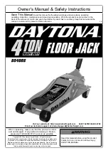
Assembly

To mount the handle turn the jack upside down. 

IMPORTANT: 

The hoses must be twisted around the 

tube as shown on the photo 

(Fig. 1)

.

WARNING: 

Do not operate the jack in this position or 

lying on the side - if so there is risk of oil spillage.

Oil mechanical parts before first use.

Air connection: ¼” WRG.

Full capacity from 9 bar/125 psi. Maximum air 

pressure:10 bar/145 psi.

Use of the jack

Transport: 

The jack is to be stored or transported 

standing on its wheels. If need be the jack may be 

transported lying on the left side observed from the 

handle side, but in this case a little oil spillage from the 

air motor might occur.

Lifting: 

Push the top button.

Lowering:

 Push the lower button. Always lower the jack 

completely in order to protect the lifting cylinder.

The handle

 offers 4 different positions: pull the handle 

and tip as required.

Maintenance

Maintenance and repair must always be carried out by 

qualified personnel.

The air-motor requires oil to lubricate the mechanical 

parts. It is recommended to use air supply with water 

separator/filter and oil lubricator.

Daily:

 Lubricate the air-motor by injecting a little oil into 

the air connection on the handle and then lift to max. 

position. Disconnect the air hose, inject further oil into 

the air connection, reconnect the air hose and press the 

lowering button to lubricate the cylinder walls.

Monthly:

 Empty water separator/filter and fill oil 

lubricator with oil. Lubricate all mechanical parts with 

a few drops of oil. At the same time inspect jack and 

extensions for damage and wear and tear.

GB

Oil level:

 refill oil through hole (8) on left-hand side of 

cabinet. Correct oil level is to the lower edge of the hole 

with the jack horizontal and the cylinder completely 

lowered.

Quantity of oil: 

25-1 2 l.; 25-1H 3 l.

Use high quality hydraulic oil, viscosity ISO VG 15. 

Never use brake fluid!

Safety Inspection

According to national legislation - minimum once a year 

though - the jack must be inspected by a professional: 

Damages, wear of cylinder bottom below plug 0258400, 

wear and tear, adjustment of the safety valve, cylinder 

and pump for leakages. Furthermore that all safety 

labels are legible.

Troubleshooting

1.  

The jack does not lift to maximum position even

though the air motor is running: refill with oil.

2.  

The air motor runs slowly or stops: the air filter

(handle drawing, no. 17) in the air connection is

blocked and needs cleaning or changing.

3.  

The load is dropping: change valve cores in pump.

PLEASE OBSERVE 

that the valve cores are to be

tightened slightly only: tighten to a torque setting of

10 Nm).

4.  

The cylinder is leaking: Change cylinder seals.

A sudden oil leak from air motor or handle might

be caused by wrong handling, e.g. if the jack has

been lying on the side. If so the oil leak (from the

reservoir) will stop, when the jack is standing on the

wheels again - but oil drips will continue for a while.

Spare parts

Replace worn or broken parts with genuine jack 

manufacturer supplied parts only. All major parts may 

not be provided after discontinuation of a model.

Destruction

Oil must be drained off and legally disposed of.

(Translation of original text)

Содержание 25-1

Страница 1: ...Brugermanual Lufthydraulisk donkraft User s guide Air hydraulic Jack Betriebsanleitung Lufthydraulischer Heber DK GB DE DK NO GB DE 25 1 Capacity 25 000 kg 25 1H Capacity 25 000 kg FR 0825030 220315 ...

Страница 2: ...ale Som andet luftværktøj kræver luftmotoren olie til smøring af bevægelige dele Det anbefales at anvende luftforsyning med filter vandudskiller og oliesmøreapparat Dagligt Smør luftmotoren ved at sprøjte lidt olie ind i håndtagets lufttilslutning med en oliekande og derefter pumpe cylinderen helt i top Tag nu luftslangen af og sprøjt yderligere lidt olie ind i lufttilslutningen tilslut slangen ig...

Страница 3: ...ricator Daily Lubricate the air motor by injecting a little oil into the air connection on the handle and then lift to max position Disconnect the air hose inject further oil into the air connection reconnect the air hose and press the lowering button to lubricate the cylinder walls Monthly Empty water separator filter and fill oil lubricator with oil Lubricate all mechanical parts with a few drop...

Страница 4: ... und Öl schmierapparat Täglich Schmieren Sie den Luftmotor indem Sie ein wenig Öl in den Luftanschluss am Griff einspritzen und diesen dann in die Maximalstellung bringen Nehmen Sie den Luftschlauch ab spritzen Sie noch mehr Öl in den Luftanschluss schließen Sie den Luftschlauch wie der an drücken Sie den Senkknopf um die Wände des Zylinders zu schmieren Monatlich Entleeren Sie den Wasserabscheide...

Страница 5: ...arateur d eau et d un lubrificateur à huile Entretien quotidien Lubrifiez le moteur pneumatique en injectant un peu d huile dans l arrivée d air de la poignée à l aide d une burette et faites sortir ensuite le vérin au maximum à l aide de la pompe Démontez le flexible d air et injectez une nouvelle fois un peu d huile dans l arrivée d air Remontez le flexible et descendez le cric et appuyez sur le...

Страница 6: ...12 25 1 25 1H DK GB DE Montering af slanger Mounting of hoses Montage von Schläuchen ...

Страница 7: ...ing Fitting 15 02 512 00 02 512 00 1 Fitting Fitting Fitting 16 02 516 00 02 516 00 2 Fitting Fitting Fitting 17 02 520 00 02 520 00 2 Skrue Screw Schraube 18 02 582 00 02 582 00 2 Seegerring Circlip Seegerring 19 02 766 00 02 766 00 2 Skive Washer Scheibe 20 44 007 24 44 007 24 1 Beskyttelsesplade Protection plate Schutzplatte 21 44 008 00 44 008 00 2 Bøsning Bushing Buchse 22 44 009 03 44 009 03...

Страница 8: ...14 90 727 30 90 728 42 ...

Страница 9: ...92 00 2 Kugle Ø6 5 Ball Ø6 5 Kuegl Ø6 5 14 02 425 00 02 425 00 1 Fitting Fitting Fitting 15 02 483 00 02 483 00 1 Prop Plug Pfropfen 16 02 503 00 02 503 00 1 Overtryksventil Pressure control valve Ûberdruckventil 17 02 511 00 02 511 00 1 Filter Filter Filter 18 02 584 00 02 584 00 1 Prop Plug Pfropfen 19 02 753 00 02 753 00 1 Fjeder Spring Feder 20 02 931 00 02 931 00 1 Seegerring Circlip Seegerri...

Страница 10: ...16 90 760 00 ...

Страница 11: ...dcylinder Main cylinder Hauptzylinder 09 033 00 1 Pakningssæt Repair kit Dichtungssatz DK De med mærkede dele leveres i komplet pakningssæt Anvend altid originale reservedele Angiv venligst altid model og reservedels nummer Alle hoveddele kan ikke forventes leveret efter produktionsophør af model GB indicate parts included in repair set Please always state model and part number Do always apply ori...

Страница 12: ...18 90 750 00 ...

Страница 13: ...atzteile kann nach Produktions Einstellung eines Modelles nicht erwartet werden Pos Art No Pcs Benævnelse Description Bezeichnung 90 750 00 Cylinder komplet Cylinder complete Zylinder komplett 1 01 031 00 1 O ring O ring O ring 2 01 055 00 1 O ring O ring O ring 3 01 081 00 1 O ring O ring O ring 4 01 153 00 1 Støttering Back up ring Stützring 5 01 287 00 1 Afstryger Scraper ring Abstreifer 6 02 3...

Страница 14: ...20 44 951 70 ...

Страница 15: ...lamp Schlauchklemme 14 02 436 00 1 Møtrik Nut Mutter 15 02 495 00 1 Fitting Fitting Fitting 16 02 506 00 1 Fitting Fitting Fitting 17 02 511 00 1 Filter Filter Filter 18 02 514 00 1 Fitting Fitting Fitting 19 44 951 71 1 Underdel Unterpart Unterteil 20 44 951 73 1 Overdel Topcover Topblech 21 44 951 77 1 Plade Plate Blech 22 44 951 78 1 Plade Plate Blech 23 44 951 82 1 Holder Holder Unterstützung ...

Страница 16: ...22 HYDRAULIK DIAGRAM HYDRAULIC CHART HYDRAULISCHES DIAGRAMM DK GB DE ...

Страница 17: ...K GB DE Special extension may not be used with other extensions Special Verlängerung darf nicht mit anderen Verlängerungen benutzt werden DE DE Art No Pcs Benævnelse Description Bezeichnung 44 021 00 1 Sadel Saddle Sattel D 145mm D 145mm D 145mm Art No Pcs Benævnelse Description Bezeichnung 63 231 00 1 V sadel V saddle V sattel DK DK GB GB DE DE Art No Pcs Benævnelse Description Bezeichnung 63 231...

Страница 18: ...chinery Safety Regulations 2008 gælder kun for UK Carsten Rødbro Jensen Fanøvej 6 DK 8800 er bemyndiget til at udarbejde det tekniske dossier Air hydraulic Jack 25 1 25 1H are in conformity with the provisions of the Machinery Di rective Directive 2006 42 EC EN1494 and The Supply of Machinery Safety Regulations 2008 UK only Mr Carsten Rødbro Jensen Fanøvej 6 DK 8800 is author ized to compile the t...

Отзывы: