User manual Version 1.0
Modbus Gateway
connected to the port. For example, Port1 connected device uses the Modbus RTU communication
protocol then “Data Mode” will be set to RTU; vise versa, if the connected device uses Modbus ASCII
then “Data Mode” will be set to ASCII.
Note: Modbus Gateway also supports TCP mode for the
“Serial Device Mode” at the port.
“Response Timeout”:
When the connected device is in slave mode will this option be required.
This option is to set the timeout period for a response from the slave port connected device, unit in
microsecond.
(2)
Master-setting list:
If the “Serial Device Mode” is set to slave, then this list will be the master list for
the Ethernet port; vise versa, if the “Serial Device Mode” is set to master, then this list will be the
slave list for the Ethernet port.
(3)
Action area:
If the “Serial Device Mode” is slave then this includes the master configuration page for
the Ethernet port; vise versa, if the “Serial Device Mode” is master then this includes the slave
configuration page for the Ethernet port. The following description is for “Serial Device Mode” set to
“Slave”.
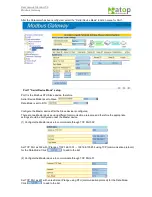
“Serial Device Mode” as “Slave” setup page
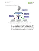
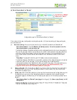
: As in Figure 1. The
Master setup (Client)
at the left
and
ID routing-table
to the right.
Master setup (Client)
: Includes the settings “Gateway TCP Port”, “Network and Netmask”, and
“Data Mode”.
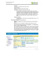
“Gateway TCP Port”
:
Modbus Gateway provides client connection to activate the TCP Port service.
“Network and Netmask”:
Combination of
“Network”
and
“Netmask”
to configure the range of
client IP to Modbus Gateway. The system does not provide shorthand
description of the Network/Netmask (e.g. 192.168.100.0/24).
Example 1: Provide any IP that the client can connect to the Modbus
Gateway, then enter 0.0.0.0 for the
“Network”
with 0.0.0.0 for the
“Netmask”
.
Example 2: Provide 192.168.100.1-192.168.100.63 range for the client to
connect to Modbus Gateway, with 192.168.100.0 for the
“Network”
and
255.255.255.192 for the
“Netmask”
.
Example 3: Provide 192.168.100.1-192.168.100.255 range for the client
to connect to Modbus Gateway, with 192.168.100.0 for the
“Network”
and 255.255.255.0 for the
“Netmask”
.
Example 4: To limit to a single IP (e.g. 192.168.100.31) for the client
connection, enter 192.168.100.31 for the
“Network”
with
255.255.255.255 for the
“Netmask”
.
“Data Mode”:
Includes RTU, ASCII, and TCP modes.
The “Data Mode” here configures the communication protocol for the master device,
and must be set to the communication protocol used by the remote Ethernet-master.
The “Data Mode” listed here is independent to the “Data Mode” in the Port-mode
setting. In other words, the master and slave can be configured with different
communication protocols, and the Modbus Gateway will perform the conversion
between different data types.
Содержание ABLELink MB5000 Series
Страница 37: ...User manual Version 1 0 Modbus Gateway and 2...


