User manual Version 1.0
Modbus Gateway
Serial Device Mode
Modbus devices are commonly labeled as Master and Slave and therefore, the Serial Device Mode of the
Modbus Gateway is also labeled as such modes, Master and Slave. When the port is set to Master, then the
Ethernet will have to be set as Slave; vise versa, when the port is set to Slave, then the Ethernet will have to
be set as Master. The following will explain the two configurations,
(I) “Serial Device Mode” as “Slave” and
(II) “Serial Device Mode” as “Master”.
(I) “Serial Device Mode” as “Slave”
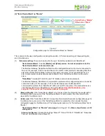
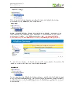
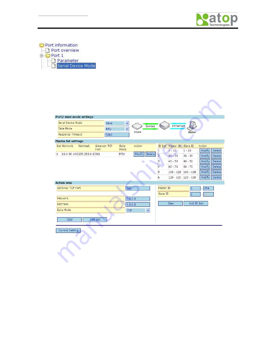
Figure 1.
Configuration page for “Serial Device Mode” as “Slave”
This page is split into three sections, (1) Port-mode setting, (2) Master-setting list, and (3) Action area.
According to the selected “Serial Device Mode”, the above-mentioned contents will differ.
(1)
Port-mode setting
: There are three options for the port, “Serial Device Mode”, “Data Mode”, and
“Response Timeout”.
“Serial Device Mode”
: Includes
[Master] and [Slave] modes. Current description is for the
“Serial Device Mode” under slave mode
.
The Modbus Gateway “Serial Device Mode” will be configured based on the device connected to the
port. For example, Port1 connected device is in slave mode (mainly provides data access for Master)
then “Serial Device Mode” will be set to slave; vise versa, if the connected device is in master mode
(mainly for accessing data from slave) then “Serial Device Mode” will be set to master.
Note: The
mode changes will show up on the configuration page.
“Data Mode”:
Includes RTU, ASCII, and TCP Modbus communication protocols.
The Modbus Gateway “Data Mode” communication protocol will be configured based on the device
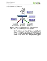
Serial Port as “Slave”
Ethernet as “Master”
Содержание ABLELink MB5000 Series
Страница 37: ...User manual Version 1 0 Modbus Gateway and 2...


