2-4
Chapter2
ZH6
In order to create a memory array, certain rules must be followed. The following set of rules
allows for optimum configurations.
!
The memory array is 64 or 72 bits wide. (depending on with or without parity)
!
Those modules can be populated in any order.
!
Supports single and double density DIMMS.
Table 2-1. Valid Memory Configurations
Bank
Memory Module
Total Memory
Bank 0, 1
(DIMM1)
8MB, 16MB, 32MB,
64MB, 128MB, 256MB
8MB ~ 256MB
Bank 2, 3
(DIMM2)
8MB, 16MB, 32MB,
64MB, 128MB, 256MB
8MB ~ 256MB
Bank 2, 3
(DIMM3)
8MB, 16MB, 32MB,
64MB, 128MB, 256MB
8MB ~ 256MB
Total System Memory
8MB ~ 512MB
Note: 1.
When you install RAM modules, we strongly suggest that you install them in the
order of filling DIMM 1~ DIMM3. If you install RAM modules disregarded this
order, you may encounter some problems. One of problems might be that you can’t
boot up the system. Another possible problem is that the BIOS won’t be able to
detect the memory you installed.
Note 2.
According to this motherboard layout design, DIMM 2 and DIMM 3 share two
banks. Therefore, please don’t install RAM modules that will occupy two banks
into both DIMM 2 and DIMM 3 at the same time. There are two main types of
RAM modules on the market now, one is single sided and the other is double sided.
The single sided RAM module doesn’t mean it only occupies one bank, and double
sided RAM module also doesn’t mean it will occupy two banks. When you want to
install RAM modules into both DIMM 2 and DIMM 3 at the same time, please
make sure how many banks of RAM the modules will occupy. For this issue, you
can refer to the specifications of your RAM module from the manufacturer.
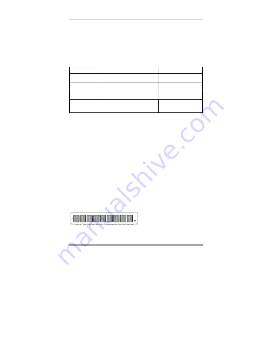
Generally, installing SDRAM modules to your motherboard is an easy thing to do. You can
refer to figure 2-3 to see what a 168-pin PC100 SDRAM module looks like.
Unlike installing SIMMs, DIMMs may
be "snapped" directly into the socket.
Note: Certain DIMM sockets have minor
physical differences. If your module
doesn't seem to fit, please do not force it into the socket as you may damaged your memory
module or DIMM socket.
Figure 2-3 PC100 Module and Component Mark
Содержание ZH6
Страница 2: ......
Страница 4: ......
Страница 8: ...1 4 Chapter1 ZH6 1 3 Layout Diagram Figure 1 2 Motherboard component location...
Страница 10: ...1 6 Chapter1 ZH6...
Страница 64: ...3 38 Chapter3 ZH6...
Страница 74: ...B 6 Appendix B ZH6...
Страница 78: ...C 4 Appendix C ZH6...
Страница 84: ...D 6 Appendix D ZH6...


