9
1
1
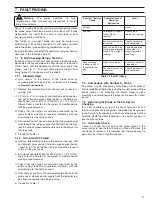
A – Standard Head
B – Twin Gland C95 Head
Cell–
Black
(Outer)
Cell+
Red
(Inner)
THC–
Blue
Test Gas
Input
THC+
White
Cable Entry
Bush
Reference
Air Input
2 Cable Entries
Threaded M16
Reference
Air Input
Test Gas
Inlet
A – Standard Head
B – Twin Gland C95 Head
Cell–
Black
(Outer)
Cell+
Red
(Inner)
THC–
Blue
THC+
White
4
CONNECTIONS
4.1
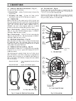
Access to Electrical Connections – Fig. 4.1
For access to the terminal block:
1
Standard Head
– remove the two screws and open the
hinged cover.
1
Twin-gland C95 Head
– remove the three screws
retaining the cover and lift off the cover and gasket.
4.2
Cable Details
Make connections to the oxygen cell via 16/0.2mm red and
blue twin copper braid with overall PVC sheath. Where the
ambient temperature in the vicinity of the probe head exceeds
100
°
C use 0.75mm
2
silicone rubber sheathed (part no.
YBM0614) and join to the screened cable via a suitable
junction box where the ambient temperature is lower.
Type K thermocouple
– 3/0.9mm
2
flat twin compensating
cable for use with NiCr/NiAl thermocouples to BS4937,
sheathing to BS6746 (part no. E35).
Type R thermocouple
– 3/0.9mm
2
flat twin compensating
cable for use with Pt/Pt 13% Rh thermocouples to BS4937,
sheathing to BS6746 (part no. E37).
4.3
Electrical Connections – Fig. 4.2
Make connections as shown in Fig. 4.2 and on the label inside
the probe head cover. The connecting cable must enter the
probe head via the bush provided (standard head) or suitable
cable glands (twin gland C95 head).
4.4
Reference Air Connections – Fig. 4.2
The reference air connector is
1
/
8
in. BSP fitted with an adaptor
to accept
1
/
4
in. i.d. x
3
/
8
in. o.d. nylon or PVC tubing (100
°
C/212
°
F
ambient maximum).
The probe requires a supply of clean, dry air at a flow rate of
500 to 1000ml/min. (1 to 2ft
3
/hr), which may be supplied from
regulated, clean, instrument air or preferably atmospheric air
from a small pump unit. Suitable air supply units are available
from the Company:
Model 003000240 – mains-powered pump unit with flow
gauge
Model 003000241 – regular unit with flow gauge.
4.5
Test Gas Inlet – Fig 4.2
The test gas inlet on standard heads is situated inside the
probe head and is sealed by a screwed plug. The inlet accepts
1
/
4
in i.d. x
3
/
8
in o.d. plastic/silicone tube.
Twin-gland C95 heads are fitted with a permanent external
6mm o.d. test gas inlet. The inlet is connected internally to the
test gas input by means of a silicone tube.
Fig. 4.1 Access to Electrical Connections
Fig. 4.2 Connections


