47
Zenith Automatic Transfer Switch | new.abb.com/low-voltage
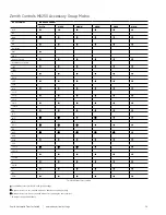
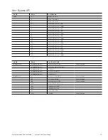
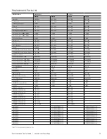
TERMINAL
TERMINAL
TERMINAL
TYPE
G1
H1
I1
Output
G2
H2
I2
Output
G3
H3
I3
Output
G4
H4
I4
Output
G5
H5
I5
Output
G6
H6
I6
Common for outputs
G7
H7
I7
Input
G8
H8
I8
Input
G9
H9
I9
Input
G10
H10
I10
Input
G11
H11
I11
Input
G12
H12
I12
Input
G13
H13
I13
Input
G14
H14
I14
Common for inputs
Table T6-2 : IO_L module connections
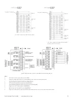
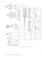
inputs I1 through I5 and outputs I7 through I13 (see Table T6-2).
Terminals G7 and G8 are always used for DS and Q2
functions, respectively, and cannot be adjusted. Depending
on the type of switch and features ordered, Terminals G1
through G5 as well as G9 through G13 may not be available
The MX350 microcontroller is a modular control and monitoring
• Flexible control and communication options to suit any low-
voltage transfer switch application.
• Small footprint.
• Modular design, which reduces the number of spare
components for maintenance and testing.
• Integrated pushbuttons and LED indicators which reduce
required external components and wiring
• Multiple communication protocols which permit simple
integration into monitoring and control systems.
• A graphical control panel that provides local control and
access to system information.
Detailed technical information on the MX350 controller is
described in the manual Entelli Switch 350 Automatic Transfer
Control System (Publication Number 1601-9071-A1).
The MX350 Graphical Display
and Keypad
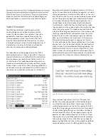
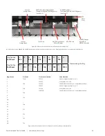
The MX350 controller features a ¼ VGA color graphical
display with status LEDs, an USB programming port
and menu-driven soft keys (see Figure Figure S6-16)
as well as dedicated control and navigational keys.
The header bar displays the hierarchical path name, the
date and time and the current password access level. The
soft-key labels are indicated on the bottom line. Soft-
keys are used for navigation, performing functions and for
acknowledgement transactions. Soft-keys labels change
to show relevant selections for the displayed screen. The
color of each soft-key label indicates its functionality. Soft-
keys are highlighted for the displayed page, unauthorized
keys are “greyed-out”, and unused keys are not displayed.
The control panel LEDs summarize the status of the
transfer switch, including the following indications:
• ALARM: indicates that there is a problem with the ATS or
that a user configurable alarm condition is active.
• TD DELAY: indicates that the controller is timing before
taking the next control action.
• XFER INHIBIT: indicates that the controller will not
automatically transfer to the other source and that operator
intervention is required to allow transfer.
• S1 (Source 1) Available LED: indicates that S1 power is
present and within user defined limits.
• S2 (Source 2) Available LED: indicates that S2 power is
present and within user defined limits.
• S1 (Source 1) Status LED: indicates that the load is
connected to S1 power.
• S2 (Source 2) Status LED: indicates that the load is
connected to S2 power.
Figure S6-16: MX350 Graphical Display Assembly.
LED Indicators
Control Keys
Soft-Keys
Graphical
Display
USB Port
Function Keys


