


47
Check the following conditions individually:
• With the circuit-breaker closed, insertion of
the withdrawable part towards the service
position must be blocked after only half a turn
of the crank in the clockwise direction, and
the travel motor on motor-operated
withdrawable parts must not be capable of
being switched on.
• With the earthing switch closed, insertion of
the withdrawable part towards the service
position must be blocked after only two
clockwise turns of the crank, and the travel
motor on motor-operated parts must not be
capable of being switched on.
Do not use force
(max. torque 25 Nm)!
2. The withdrawable part must only be movable
from the service position into the test/
disconnected position with the circuit-breaker
open.
Check this condition as follows:
• With the circuit-breaker closed, withdrawal
movement of the withdrawable part must be
blocked after only half a turn of the crank in
the anti-clockwise direction, and the travel
motor on motor-operated withdrawable parts
must not be capable of being switched on.
3. Closing of the circuit-breaker must only be
possible when the withdrawable part is in the
defined test/disconnected position or service
position.
The control wiring plug 8.1 must previously have
been inserted.
Check this condition as follows:
• It must not be possible to close the circuit-
breaker with the withdrawable part in any
position between the test/disconnected
position and the service position.
• Enabling of switching when the withdrawable
part moves into the service position is
effected electrically by operation of auxiliary
switch -S6 in the breaker housing (for type A),
or of auxiliary switch -S9 in the withdrawable
assembly (for type B), and mechanically
slightly earlier; the latter corresponds to a
position approximately half a turn of the crank
before stop.
• For motion into the test/disconnected
position, the same enabling conditions apply
analogously, in this case by means of auxiliary
switch -S6 in the breaker housing(for type A)
or the auxiliary switch -S8 in the withdrawable
assembly (for type B).
4. It must only be possible to open the circuit-
breaker (manually) when the withdrawable part
is in the service position or test/disconnected
position and the control voltage has failed.
Check this condition.
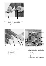
5. Withdrawable parts with order-related blocking
magnet -Y0 may not be moved in case of control
power failure, or when there is no control power.
Do not forcibly move blocked withdrawable
parts! The blocking magnet -Y0 is only present
on manually operated withdrawable parts.
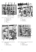
Releasing the blocking magnet -Y0.
• Remove front plate 9.2,
• Disengage blocking magnet -Y0 by pulling the
magnet armature,
• While doing so, turn crank 5 about one half
turn (either direction of rotation is permissible).
The blocking magnet is only active in the test
position and service position. In intermediate
positions it has no effect.
6. Disconnection of the control wiring plug 8.1 as
well as later insertion must be blocked in the
withdrawable part’s service position.
Check this condition.
8.6
Spare parts, auxiliary materials, lubricants
8.6.1
Spare parts
When parts are required, the serial number of the
relevant withdrawable breaker part or circuit-
breaker should always be quoted. Setting
instructions are to be requested separately.
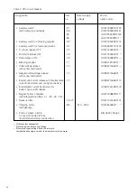
Circuit-breaker VD4:
• Shunt release, auxiliary switch:
For notes on settings see drawing
GCE 717 96 11
• Charging motor with gearbox:
No special notes required
(table 1)
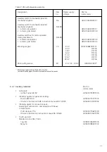
Withdrawable assembly of VD4:
• Manually moveable withdrawable assembly :
– type A:
For notes on settings see drawing
GCE 7003570, sheet 1 and 2
– type B:
For notes on settings see drawing
GCE 7003570, sheet 1 and 2.
• Motor-driven withdrawable parts:
For notes on settings see drawing
GCE 7003571
• Blocking magnet -Y0:
For notes on settings see drawing
GCE 7003820, sheet 1.
(table 2)
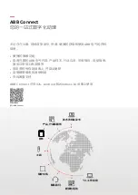
Содержание VD4 Series
Страница 2: ......
Страница 55: ...ABB Connect ABB Connect ABB ABB ABB Connect iOS Android Windows 10...